Vehicle accessory touch switch
a technology of touch switch and vehicle accessory, which is applied in the direction of instruments, pulse technique, transportation and packaging, etc., can solve the problems of vehicle accessory touch switch malfunction, difficult to take out items from the door pocket, etc., and achieve the effect of avoiding a malfunction
- Summary
- Abstract
- Description
- Claims
- Application Information
AI Technical Summary
Benefits of technology
Problems solved by technology
Method used
Image
Examples
first embodiment
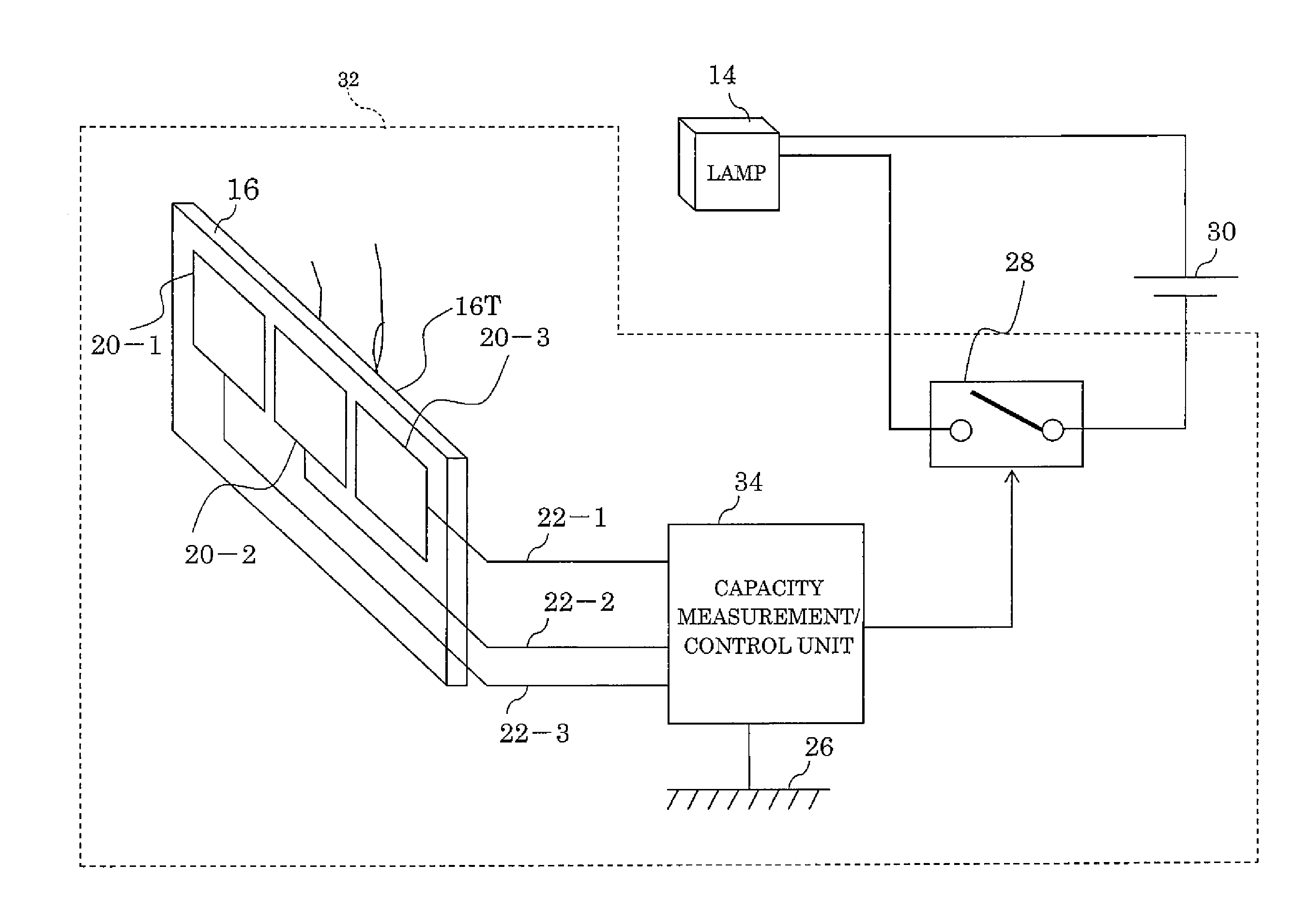
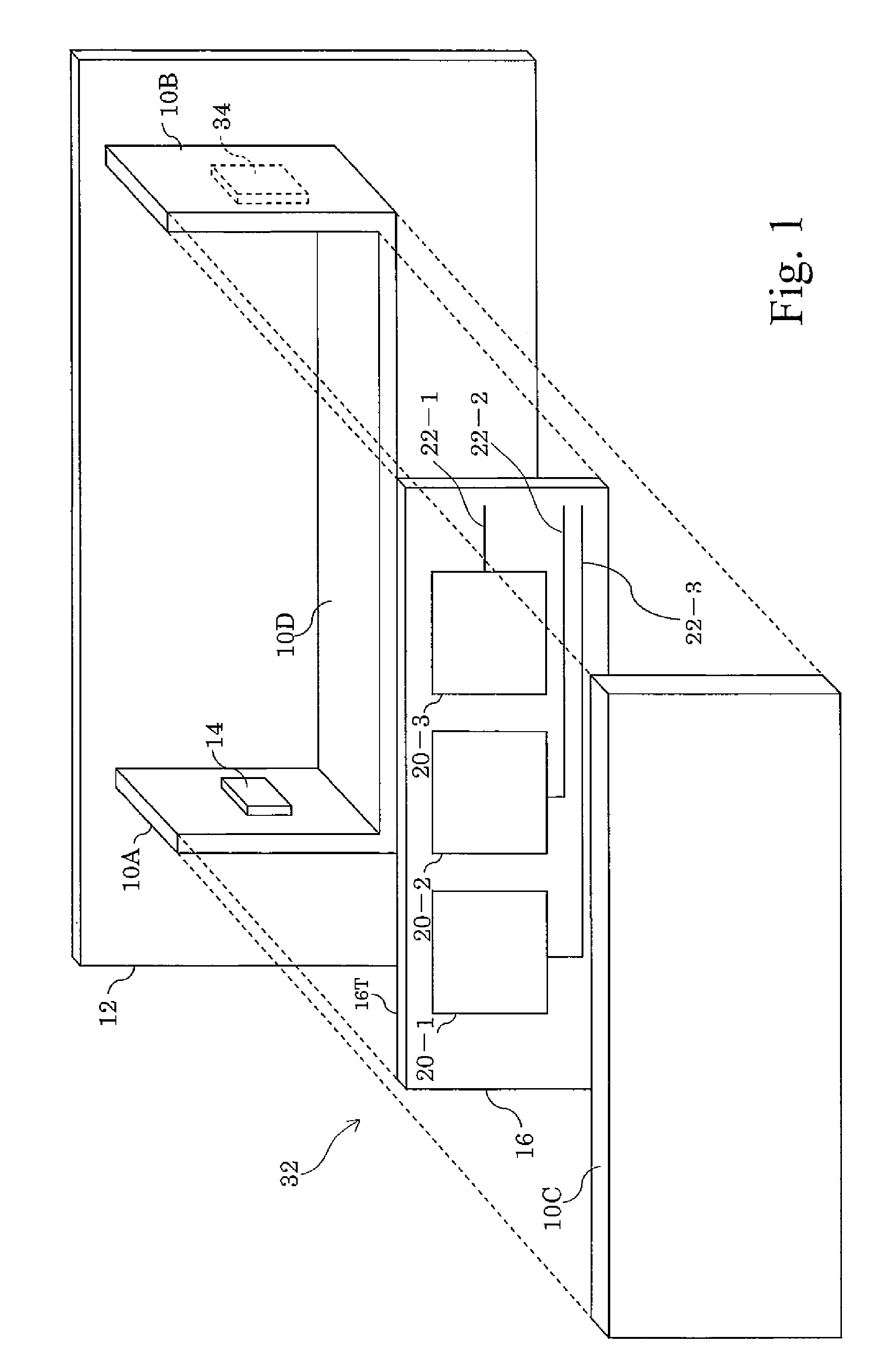
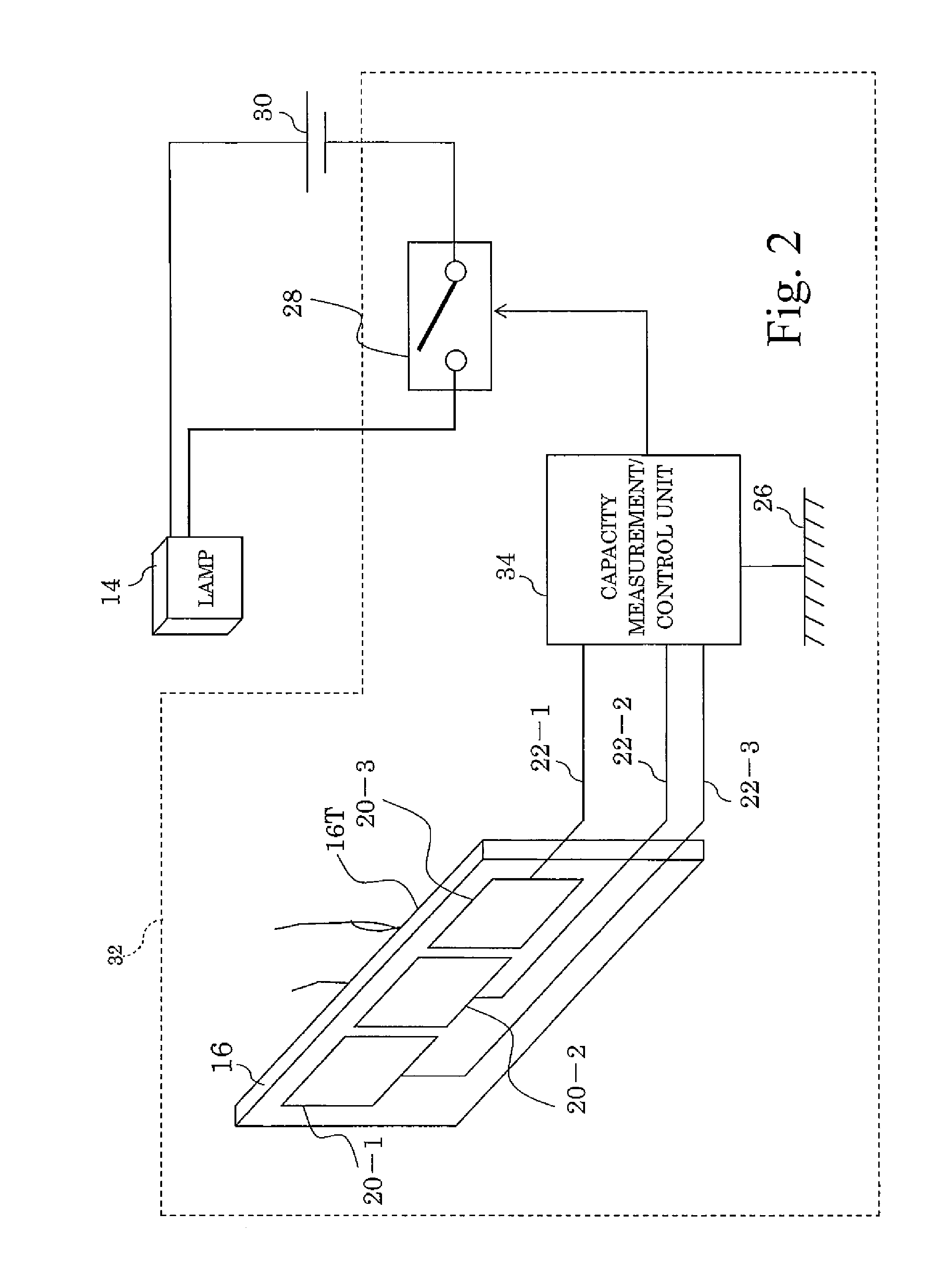
[0025]FIG. 1 shows an exploded view of a state where a vehicle accessory touch switch 32 according to the invention is incorporated in a door pocket. FIG. 2 shows a structure of the vehicle accessory touch switch 32. Similar component parts corresponding to those of FIG. 8 and FIG. 9 are denoted by similar reference numerals, and their descriptions will be omitted. The vehicle accessory touch switch 32 has the touch plate 16 provided with three conductor plates 20-1 to 20-3. The conductor plates 20-1 to 20-3 are connected with conductor wires 22-1 to 22-3, and the conductor wires 22-1 to 22-3 are connected to a capacity measurement / control unit 34 which is built into the side wall 10B. The touch plate 16 is fixed to the inside surface of the main wall 10C of the door pocket. The example of FIG. 1 performs controls to turn on the lamp 14 disposed within the door pocket in the same manner as in the example of FIG. 8.
[0026]The structure of the vehicle accessory touch switch 32 will be ...
second embodiment
[0043]A vehicle accessory touch switch 36 according to the invention will now be described with reference to FIG. 6. Similar component parts corresponding to those of the vehicle accessory touch switch 32 of FIG. 2 are denoted by similar reference numerals, and their descriptions will be omitted. The vehicle accessory touch switch 36 has the touch plate 16 of the vehicle accessory touch switch 32 replaced with a touch unit 38.
[0044]The touch unit 38 is provided with conductor plates 20-1 to 20-3, and supporting dielectric bodies 38-1 to 38-4.
[0045]The supporting dielectric bodies 38-1 to 38-4 are formed having a pillar shape. Their sectional shape perpendicular to their stretched direction is arbitrary. Here, the supporting dielectric bodies 38-1 to 38-4 are formed to have the shape of a substantially square pillar. The supporting dielectric bodies 38-1 to 38-4 have a length in the stretched direction substantially equal to the length in the vertical direction of the conductor plate...
PUM
 Abstract
Description
Claims
Application Information
 - R&D
- Intellectual Property
- Life Sciences
- Materials
- Tech Scout
- Unparalleled Data Quality
- Higher Quality Content
- 60% Fewer Hallucinations
Browse by: Latest US Patents, China's latest patents, Technical Efficacy Thesaurus, Application Domain, Technology Topic, Popular Technical Reports.
© 2025 PatSnap. All rights reserved.Legal|Privacy policy|Modern Slavery Act Transparency Statement|Sitemap|About US| Contact US: help@patsnap.com


