Sound absorbing structure built into luggage compartment of vehicle

a technology of sound absorption structure and vehicle, which is applied in the direction of roofs, walls, transportation and packaging, etc., can solve the problems of difficult to attenuate or dampen low-frequency sound/noise below 500 hz, and achieve the effect of efficient absorption of low-frequency nois

Inactive Publication Date: 2012-01-10
YAMAHA CORP
View PDF15 Cites 5 Cited by
  • Summary
  • Abstract
  • Description
  • Claims
  • Application Information

AI Technical Summary

Benefits of technology

[0009]It is an object of the present invention to provide a sound absorbing structure which is built into a luggage compartment so as to efficiently absorb low-frequency sound / noise such as road noise (or running noise) caused by a vehicle traveling on a road.
[0012]It is possible to equip the body of a vehicle with at least two of the first, second, and third sound absorbing structures, which are arbitrarily combined together.
[0014]The sound absorbing structure of the present invention converts sound waves into vibrations so as to consume acoustic energy as mechanical energy, thus absorbing sound. By appropriately setting parameters and dimensions, the sound absorbing structure efficiently absorbs low-frequency noise such as road noise.

Problems solved by technology

With the above technologies, it is difficult to attenuate or dampen low-frequency sound / noise below 500 Hz.

Method used


Image

  • Sound absorbing structure built into luggage compartment of vehicle
  • Sound absorbing structure built into luggage compartment of vehicle
  • Sound absorbing structure built into luggage compartment of vehicle

Examples


first embodiment

1. First Embodiment

(1-1) Vehicle

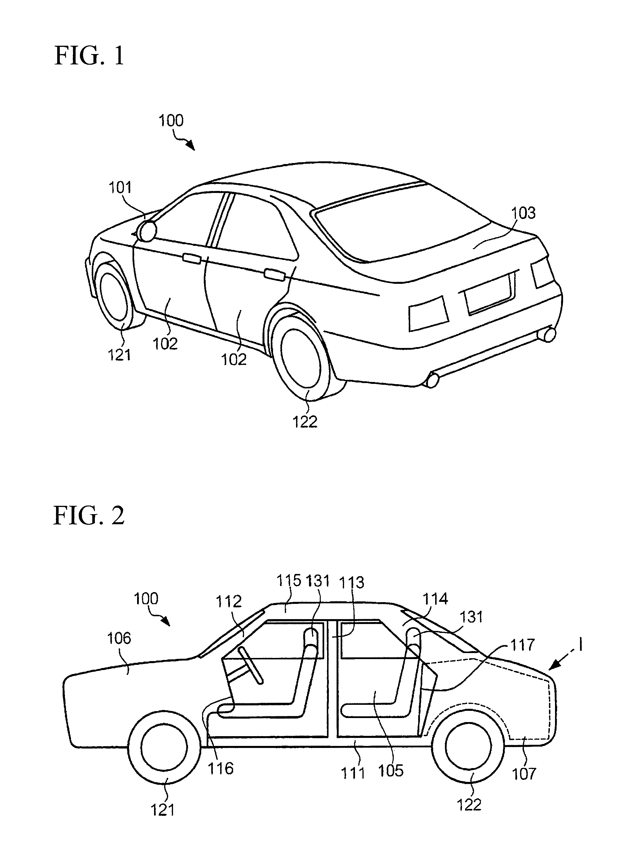
[0031]FIG. 1 is a perspective view showing the exterior appearance of a vehicle 100, i.e. a four-door sedan, in accordance with a first embodiment of the present invention. In the vehicle 100, a hood 101, doors 102, and a trunk door 103 are attached to a chassis forming the frame of a body in open / closed manners. Left / right front wheels 121 are attached to the front side of the chassis, while left / right rear wheels 122 are attached to the rear side of the chassis.

[0032]FIG. 2 is a side view partly in section diagrammatically showing the body of the vehicle 100. The chassis of the vehicle 100 includes a base 111, front pillars 112, center pillars 113, rear pillars 114 (wherein the pillars 112-114 are extended upwardly from the base 111), a roof 115 (which is supported by the pillars 112-114), an engine partition board 116 (which partitions the inside space of the vehicle 100 into a cabin 105 and an engine compartment 106), and a trunk partition board 1...

second embodiment

2. Second Embodiment

[0075]A sound absorbing structure according to a second embodiment of the present invention will be described with reference to FIGS. 7A and 7B, and FIGS. 8 and 9. The second embodiment is characterized by employing pipes as sound absorbing structures installed in the trunk 107 of the vehicle 100. The parts identical to those used in the first embodiment are designated by the same reference numerals, thus avoiding duplicate descriptions.

(2-1) Constitution

[0076]FIG. 7A is a plan view showing the upper portion of the trunk 107, and FIG. 7B is a cross-sectional view of the trunk 107. A trunk floor mat M composed of an air-permeable material is laid on the trunk floor F of the trunk 107. FIG. 7A is a simplified illustration showing the trunk floor F below the trunk floor mat M which is removed, whereas, in actuality, the trunk floor mat M is tightly laid on the trunk floor F. Two sound absorbing structures 30 (i.e. 30L and 30R) each including a plurality of pipes are...

third embodiment

3. Third Embodiment

[0088]A third embodiment of the present invention will be described with reference to FIG. 10, wherein parts identical to those of the first embodiment are designated by the same reference numerals, thus avoiding duplicate descriptions.

[0089]The third embodiment features a Helmholtz sound absorbing structure 40, which is disposed on the trunk floor F of the trunk 107 and which is opened toward the rear wheel 122 causing high sound pressure similar to the sound absorbing structure 30 including the pipes 31 whose openings 33 are directed to the rear wheel 122.

[0090]FIG. 10 is a cross-sectional view of the Helmholtz sound absorbing structure 40 according to the third embodiment of the present invention. The Helmholtz sound absorbing structure 40 is constituted of a housing 41 having a rectangular parallelepiped shape enclosing a hollow space and a pipe member 43 inserted into an insertion hole 42 made on the housing 41 at a prescribed position directing toward the tr...


PUM


Abstract

A sound absorbing structure is constituted of a vibration plate and a rear air layer and is installed in a luggage compartment or trunk which is separated from a cabin in a vehicle. Sound waves entering into the luggage compartment drive the vibration plate to vibrate so that acoustic energy is converted into mechanical energy and is consumed by way of vibration of the vibration plate. By appropriately setting parameters and dimensions, the sound absorbing structure efficiently absorbs low-frequency sound such as road noise occurring due to friction of wheels of the vehicle traveling on a road.

Description

BACKGROUND OF THE INVENTION[0001]1. Field of the Invention[0002]The present invention relates to sound absorbing structures built into luggage compartments of vehicles.[0003]The present application claims priority on Japanese Patent Application No. 2008-261015, the content of which is incorporated herein by reference.[0004]2. Description of the Related Art[0005]Various technologies for absorbing sound / noise entering into cabins of vehicles have been developed and disclosed in various documents such as Patent Documents 1 and 2, which disclose fibered mats and carpets for absorbing sound in trunks or boots.[0006]Patent Document 1: Japanese Unexamined Patent Application Publication No. H11-99869[0007]Patent Document 2: Japanese Patent No. 3836402[0008]With the above technologies, it is difficult to attenuate or dampen low-frequency sound / noise below 500 Hz.SUMMARY OF THE INVENTION[0009]It is an object of the present invention to provide a sound absorbing structure which is built into a...

Claims


Application Information

Patent Timeline
Patent Type & Authority Patents(United States)
IPC IPC(8): E04B1/82
CPCB60R13/011B60R13/08B60R13/0815
Inventor NAKAMURA, YASUTAKATANASE, RENTOYOSHIDA, ATSUSHIMATSUSHITA, MASARU
Owner YAMAHA CORP
Why Eureka
Try Eureka