
System and method for controlling a ventilation unit of a vehicle

a technology for ventilation units and vehicles, applied in vessel parts, transportation and packaging, vessel construction, etc., can solve the problems of frequent cycle of ventilation units, affecting the health of individuals, and affecting the safety of passengers, so as to achieve the effect of convenient installation

Inactive Publication Date: 2012-01-10
CALSONICKANSEI NORTH AMERICA
View PDF5 Cites 27 Cited by
  • Summary
  • Abstract
  • Description
  • Claims
  • Application Information

AI Technical Summary

Benefits of technology

"The present invention provides a sensor system and method for controlling the ventilation unit of a vehicle between outside air and recirculation modes. The system includes an air quality sensor and a controller that receives a user-selectable air quality threshold and adjusts the inlet air valve accordingly. The system can adapt to the current driving condition of the vehicle and can be easily installed as an aftermarket device. The technical effects of the invention include improved air quality control, improved driving safety, and improved user experience."

Problems solved by technology

Drivers and their passengers are frequently exposed to the harmful pollutants and unpleasant odors of gasoline and diesel exhaust emissions.
Unfortunately, high concentrations of these gases tend to penetrate the vehicle interior through the ventilation system, and can compromise the health of individuals.
A problem that occurs with automated positioning of the inlet air valve based on air quality sensing is that the ventilation unit can repeatedly cycle between the outside air and the recirculation modes, particularly when the vehicle is operated in congested city traffic.
This changing noise level can be annoying to the vehicle occupants, and can cause excessive wear on the air inlet valve and its corresponding components.
Moreover, automated positioning prevents the vehicle occupants from being able to make tradeoffs between their desired cabin air quality and an acceptable amount of cycling between the outside air and the recirculation modes.
In addition, conventional sensor systems do not make the distinction between driving conditions that typically experience lower pollutant levels, i.e., relatively high speed highway and / or rural driving, and those that typically experience higher pollutant levels, i.e., lower speed city driving.
Unfortunately, however, a vast majority of new and pre-owned passenger vehicles are not equipped with any such sensors, notwithstanding their limitations.
Thus, concerned individuals have no option but to manually switch between an outside air mode and a recirculation mode when they determine that pollutant levels of the outside air are undesirably high.
Although a driver could switch to recirculation mode manually, the driver may forget to switch back to outside air mode.
By remaining in the recirculation mode, the windows could fog or the carbon dioxide level could increase resulting in a decrease in the oxygen level.
Fogged windows and / or a decreased oxygen level in the cabin could compromise the safety of the driver and his or her passengers.
Furthermore, some gaseous pollutants are undetectable by humans.
Therefore, the individual may not realize that the pollutant level within the vehicle interior has become undesirably high, and that he or she should switch to recirculation mode.
Even when gaseous pollutants are detectable, the pollutant level in the vehicle may have already become excessively high by time the individual is finally able to detect it.
As such, manually switching to recirculation mode once noxious odors are detected may be disadvantageous since there is already a significant quantity of pollutants in the recirculated air.

Method used


Image

  • System and method for controlling a ventilation unit of a vehicle
  • System and method for controlling a ventilation unit of a vehicle
  • System and method for controlling a ventilation unit of a vehicle

Examples


Embodiment Construction

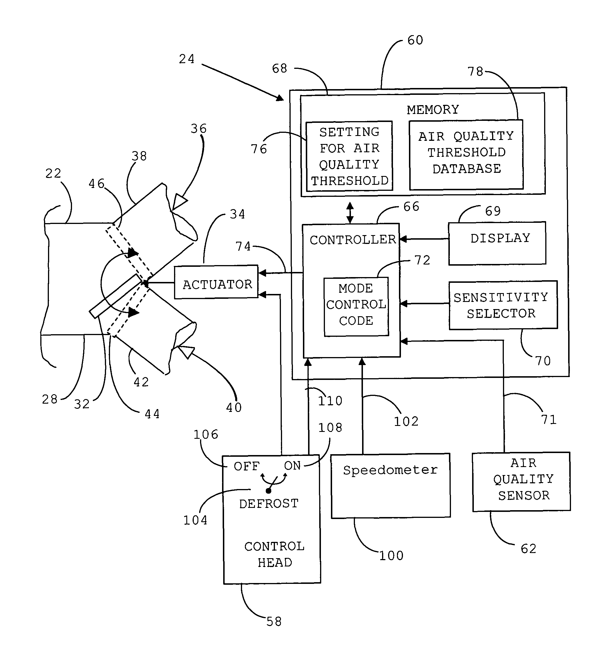
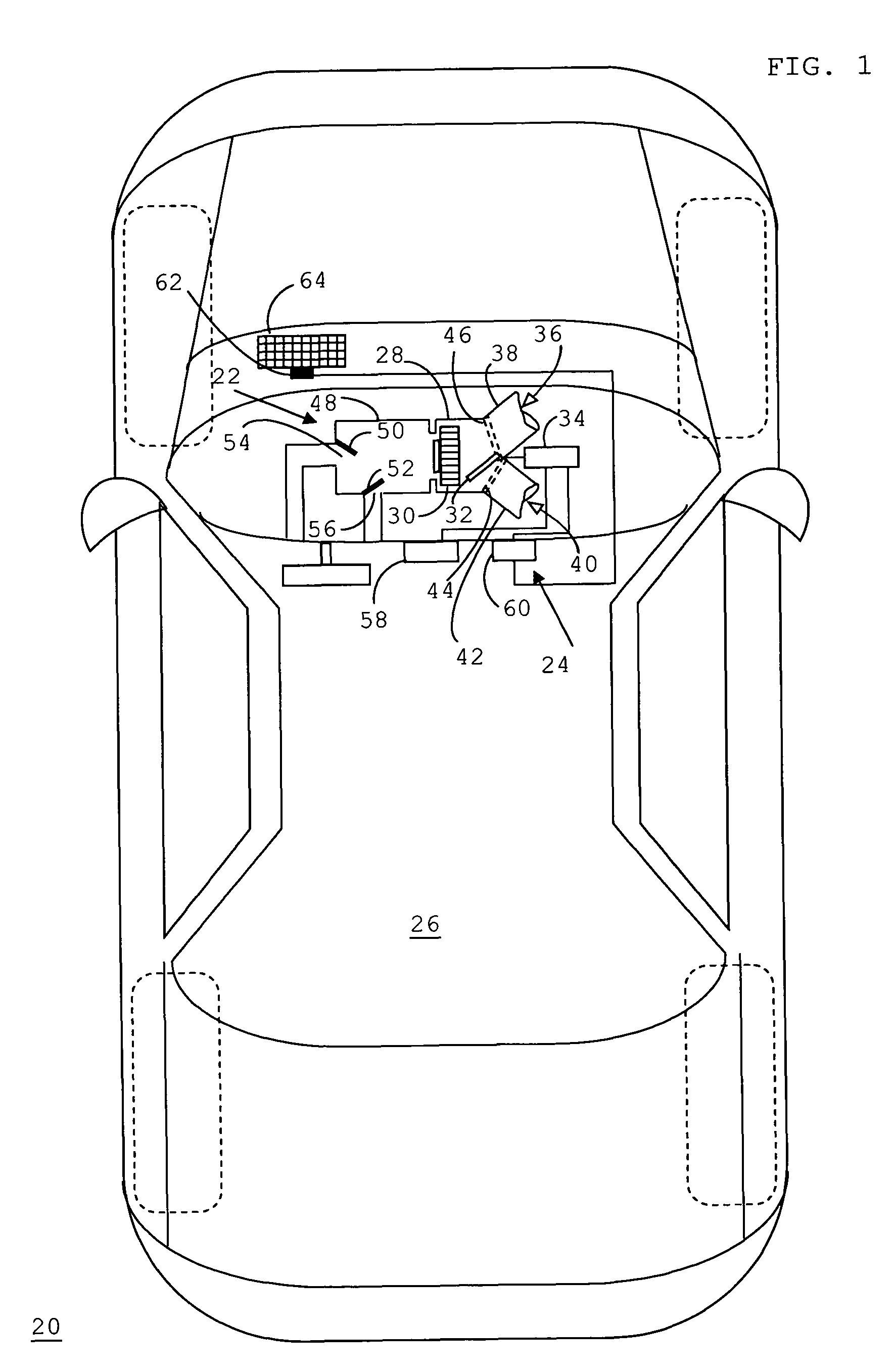
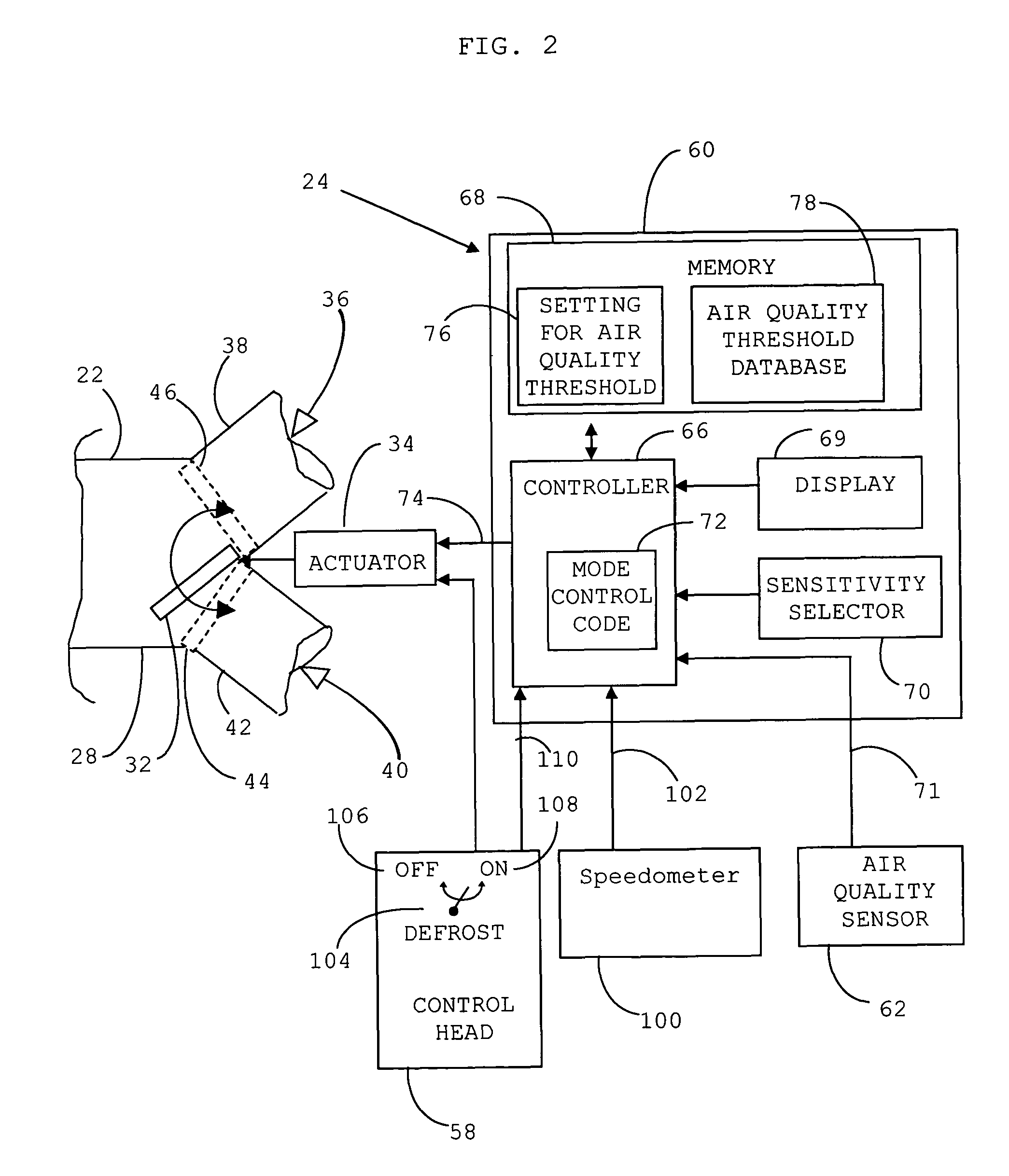
[0022]FIG. 1 shows a top schematic view of a vehicle 20 having a ventilation unit 22 controlled by a sensor system 24 in accordance with a preferred embodiment of the present invention. Vehicle 20 may be any passenger or cargo vehicle for which airflow to an interior compartment 26 is controlled. Ventilation unit 22 may be a conventional vehicular heating, ventilation, and air conditioning (HVAC) unit. However, that is not a limitation of the present invention. Rather, ventilation unit 22 may simply include means for selectively enabling inlet of outside air or recirculated air from interior compartment 26, as well known to those skilled in the art. Accordingly, only those elements of ventilation unit 22 that are pertinent to the present invention are described herein.

[0023]Ventilation unit 22 includes an air intake duct 28 having an inlet air blower 30 driven by a blower motor (not shown) to force inlet air past additional elements of ventilation unit 22, such as a filter and evapo...


PUM


Abstract

A sensor system (24) for controlling a ventilation unit (22) of a vehicle (20) includes a sensitivity selector (70) for enabling a user to select a setting (76) corresponding to an air quality threshold (94, 98), and an air quality sensor (62) proximate an exterior of the vehicle (20) for detecting an air quality parameter (71). A controller (66) is responsive to the selector (70) and the sensor (62), and is in communication with an inlet air valve (32) of the ventilation unit (22). A method (118) of operating the sensor system (24) entails receiving a current value of the air quality parameter (71) at the controller (66) for comparison with the air quality threshold (94, 98). The controller (66) generates a switch signal (74) in response to the comparison for adjusting the inlet air valve (32) between an outside air mode (44) and a recirculation mode (46).

Description

TECHNICAL FIELD OF THE INVENTION[0001]The present invention relates to the field of vehicular heating, ventilation, and air conditioning (HVAC) units. More specifically, the present invention relates to a system for controlling the ventilation unit of a vehicle for switching between an outside air mode and a recirculation mode.BACKGROUND OF THE INVENTION[0002]Drivers and their passengers are frequently exposed to the harmful pollutants and unpleasant odors of gasoline and diesel exhaust emissions. Levels of exhaust gases at major metropolitan intersections, in stop-and-go conditions, on congested freeways, in tunnels, or behind high-polluting vehicles, such as trucks or old cars, can be one hundred to one thousand times higher than concentrations of pollutants in the surrounding area. These pollutants include carbon monoxide (CO), hydrocarbons (HC), volatile organic compounds (VOC), nitrogen oxides (NOx), and so forth. Unfortunately, high concentrations of these gases tend to penetr...

Claims


Application Information

Patent Timeline
Patent Type & Authority Patents(United States)
IPC IPC(8): B61D27/00
CPCB60H1/00764B60H1/008B60H1/00849B60H3/0085
Inventor MATHUR, GURSARAN DASSCHELL, CARL HUGH
Owner CALSONICKANSEI NORTH AMERICA
Learn More