
Portable electronic device

a portable electronic device and battery technology, applied in the direction of sustainable buildings, transportation and packaging, instruments, etc., can solve the problems of inconvenience to users, consuming a lot of electric power to operate the buttons, and depleting the electric power of the battery of the portable electronic devi

Inactive Publication Date: 2012-01-10
SHENZHEN FUTAIHONG PRECISION IND CO LTD +1
View PDF6 Cites 1 Cited by
  • Summary
  • Abstract
  • Description
  • Claims
  • Application Information

AI Technical Summary

Benefits of technology

[0004]Portable electronic devices, such as mobile phones, personal digital assistants (PDA), and laptop computers, are widely used. Most portable electronic devices have buttons mounted thereon for operation. However, operating the buttons consumes a lot electric power over when the device is in standby modes. Also, frequent usage of the buttons, e.g., using the buttons to edit short messages or to play games, may dramatically deplete the electric power of the battery of the portable electronic device. Thus, the portable electronic device needs to be frequently charged, which causes inconvenience to the user thereof.

Problems solved by technology

However, operating the buttons consumes a lot electric power over when the device is in standby modes.
Also, frequent usage of the buttons, e.g., using the buttons to edit short messages or to play games, may dramatically deplete the electric power of the battery of the portable electronic device.
Thus, the portable electronic device needs to be frequently charged, which causes inconvenience to the user thereof.

Method used


Image

  • Portable electronic device
  • Portable electronic device
  • Portable electronic device

Examples


Embodiment Construction

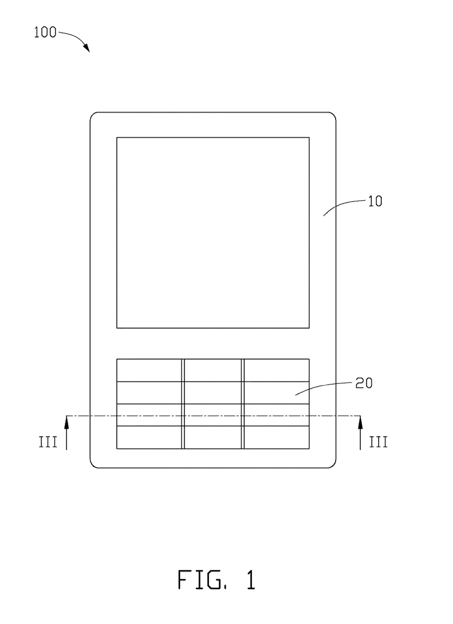
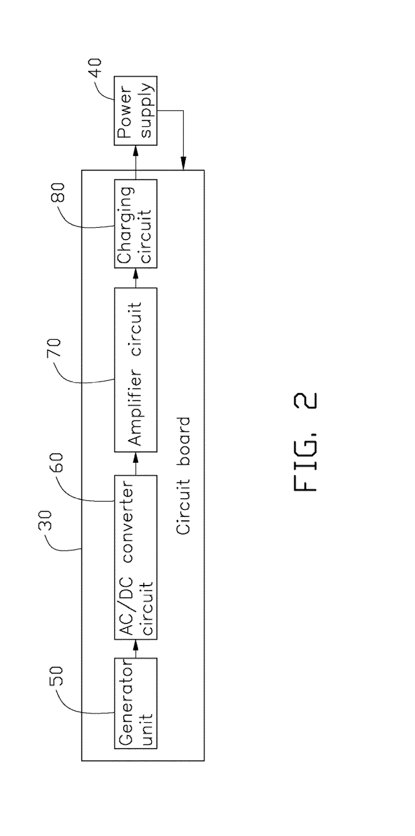
[0011]FIG. 1 schematically shows a portable electronic device 100 according to an exemplary embodiment. In the present disclosure, the portable electronic device 100 is a mobile phone, but can also be a personal digital assistant (PDA), a game console, a laptop computer, etc. Also referring to FIG. 2, the portable electronic device 100 includes a housing 10, a plurality of buttons 20, a circuit board 30, a power supply 40, a generator unit 50, an alternating current / direct current (AC / DC) converter circuit 60, an amplifier circuit 70, and a charging circuit 80.

[0012]The housing 10 can be a conventional case used in portable electronic devices. The buttons 20 are mounted on an outside surface of the housing 10. The buttons 20 can be pressed to move perpendicularly to the surface and rebound when the pressing force is removed. The movements of the buttons 20 can activate corresponding operating circuits, thereby generating electronic signals to operate the portable electronic device 1...


PUM


Abstract

A portable electronic device includes a housing, a plurality of buttons mounted on the housing for operating the portable electronic device, a power supply received in the housing for supplying working electric power to the portable electronic device, and a generator unit. The generator unit includes a plurality of magnetic components mounted on the buttons and a plurality of windings received in the housing and electronically connected to the power supply. Thereby induced currents for charging the power supply are generated when the magnetic components are moved with the movements of the operated buttons.

Description

BACKGROUND[0001]1. Technical Field[0002]The present disclosure relates to portable electronic devices, and particularly to a power saving portable electronic device.[0003]2. Description of Related Art[0004]Portable electronic devices, such as mobile phones, personal digital assistants (PDA), and laptop computers, are widely used. Most portable electronic devices have buttons mounted thereon for operation. However, operating the buttons consumes a lot electric power over when the device is in standby modes. Also, frequent usage of the buttons, e.g., using the buttons to edit short messages or to play games, may dramatically deplete the electric power of the battery of the portable electronic device. Thus, the portable electronic device needs to be frequently charged, which causes inconvenience to the user thereof.[0005]Therefore, there is room for improvement within the art.BRIEF DESCRIPTION OF THE DRAWINGS[0006]Many aspects of the present portable electronic device using the same ca...

Claims


Application Information

Patent Timeline
Patent Type & Authority Patents(United States)
IPC IPC(8): H02K7/06
CPCG06F1/1626G06F1/1635H01H13/70H02J7/32H04M1/23Y02B40/90H01H2239/024H01H2223/04Y02B40/00
Inventor ZHANG, TAO
Owner SHENZHEN FUTAIHONG PRECISION IND CO LTD
Learn More