Monitoring device for a laser machining device

a monitoring device and laser machining technology, applied in the direction of manufacturing tools, television systems, instruments, etc., can solve the problem that the use of the physical property of “heat conduction” cannot be done to the extent, and achieve the effect of simple detection of errors

Inactive Publication Date: 2012-01-10
FFT PRODIONSSYST
View PDF20 Cites 69 Cited by
  • Summary
  • Abstract
  • Description
  • Claims
  • Application Information

AI Technical Summary

Benefits of technology

[0009]In contrast to the prior art, the present invention has the objective of refining a monitoring device for a laser machining device of the above-mentioned type in such a way that, during the serial production of workpieces in which the laser beam travels repeatedly along a prescribed, adjustable trajectory, simple detection of an error can be achieved.
[0025]It has been found to be particularly advantageous for a diffractive grid to be provided in front of the laser pointer, and to be used to expand the laser beam of the laser pointer to form a strip structure or grid structure that is projected into the spatial section of the machining process. The strip pattern or grid pattern then becomes visible in the camera image, which allows an especially easy adjustment of the sensor or sensors in terms of orientation as well as in terms of the position of the sensors.

Problems solved by technology

This is intended to take into consideration the fact that the laser protection walls used so far are exposed to a considerably higher power density in the new high-power lasers, so that utilizing the physical property of “heat conduction” cannot be done to the extent that was done earlier.

Method used


Image

  • Monitoring device for a laser machining device
  • Monitoring device for a laser machining device

Examples


Embodiment Construction

[0033]Additional objectives, advantages, application possibilities and configurations of the present invention can be gleaned from the description below of an embodiment making reference to the drawing. Here, all of the described and / or depicted features, either alone or in any meaningful combination, constitute the subject matter of the invention, also irrespective of their compilation in the claims or of their referral back to other claims.

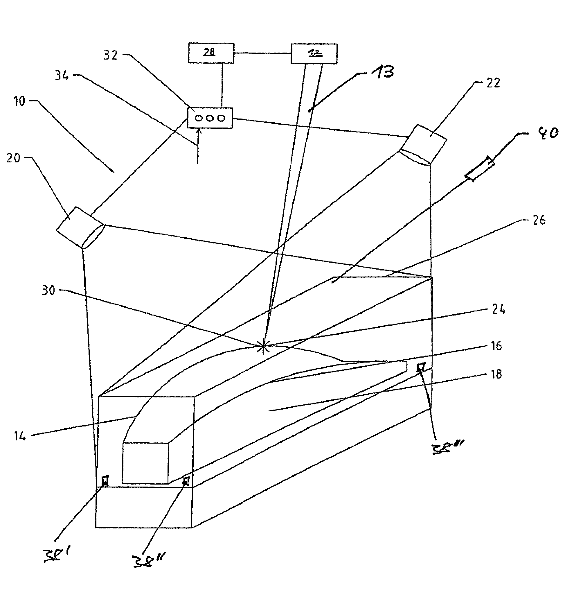
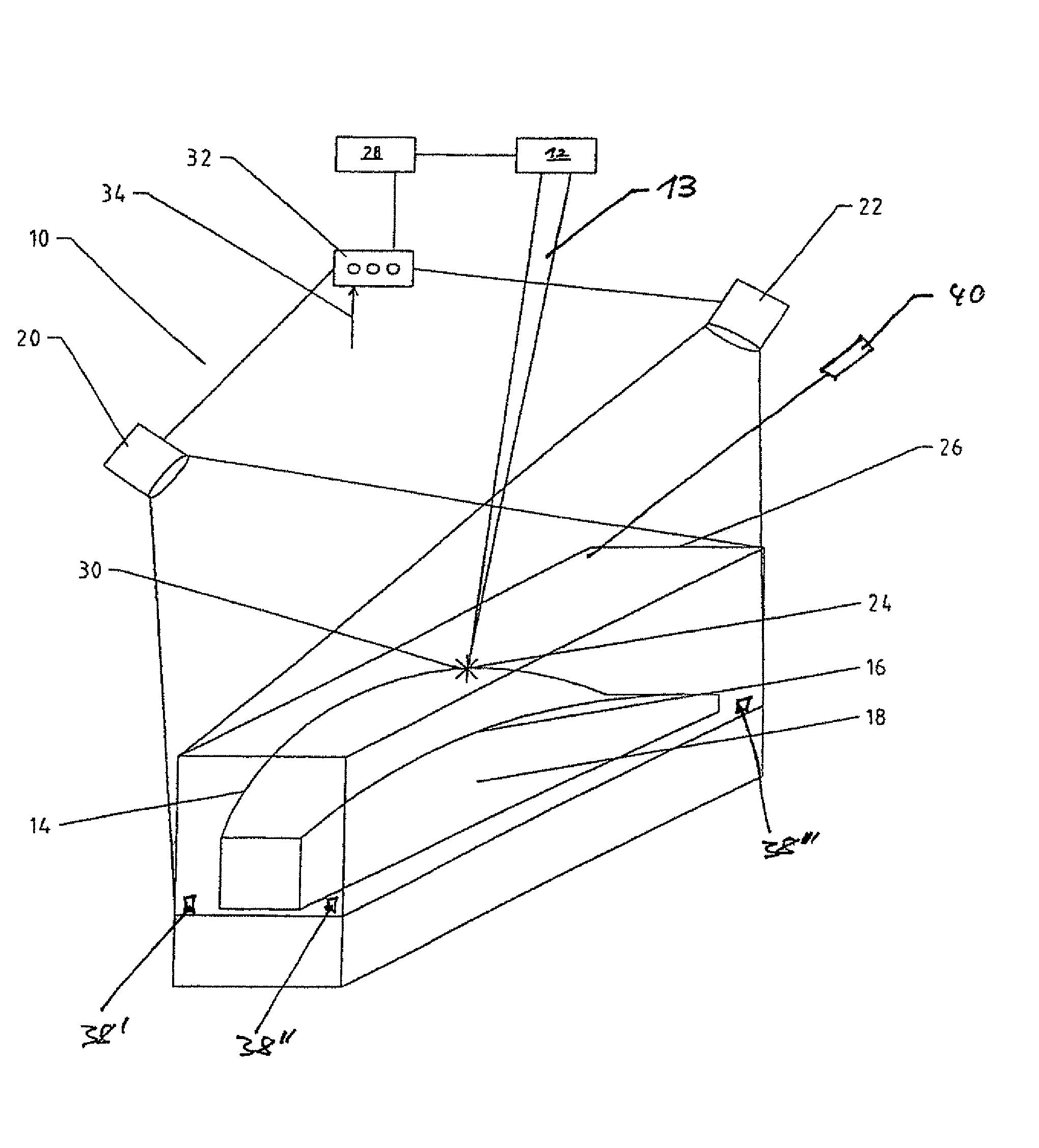
[0034]The single FIGURE schematically shows an embodiment of a monitoring device 10 according to the invention for a laser machining device 12, comprising one or more laser beams 13. The laser beam or beams travel in a prescribed, adjustable trajectory along a workpiece 18 for purposes of machining it, whereby this machining operation is repeated from one workpiece 18 to the next during serial production. The machining of the workpiece can be carried out in the form of welding, soldering, cutting, drilling or the like.

[0035]The monitoring device...


PUM

PropertyMeasurementUnit
thresholdaaaaaaaaaa
laser-specific wavelengthaaaaaaaaaa
wavelengthaaaaaaaaaa

Abstract

A monitoring device (10) for a laser machining device (12) that has one or more laser beams (13) that are displaced along a predetermined adjustable trajectory (14, 16) along a workpiece (18) includes one or more sensors (20, 22) which monitor(s) the processing signal (24) of the machining process in a three-dimensional section (26). The one or more sensors (20, 22) activate an alarm device or interrupter (28) for the one or more laser beams (13) of the laser machining device (12) if the one or more process signals (24) in the section (26) exceed a predetermined threshold value or fall short of it, the one or more sensors (20, 22) being independent of the laser machining device (12).

Description

CROSS-REFERENCE TO RELATED APPLICATIONS[0001]This application is a national stage application (under 35 U.S.C. §371) of PCT / EP2007 / 007231, filed Aug. 16, 2007, which claims benefit of German application 10 2006 038 795.3, filed Aug. 18, 2006.DESCRIPTION[0002]The invention relates to a monitoring device for a laser machining device comprising one or more laser beams that travel in a prescribed, adjustable trajectory along a workpiece for purposes of machining it by means of welding, cutting, drilling or the like, and whereby this machining operation is repeated from one workpiece to the next during the serial production of the workpieces.STATE OF THE ART[0003]German utility model DE 94 03 822 U1 discloses a monitoring device for laser beams in which an optically transparent component of the machining optical system is connected to a measuring device for purposes of detecting scattered radiation. The control unit is configured in such a way that the laser radiation is switched off whe...

Claims


Application Information

Patent Timeline
Patent Type & Authority Patents(United States)
IPC IPC(8): G08B21/00
CPCB23K26/032B23K26/422B23K26/426B23K26/428B23K26/702B23K26/705B23K26/707
Inventor HEBERER, ERWIN MARTIN
Owner FFT PRODIONSSYST
Why Eureka
Try Eureka