Multi-mode transmitter having adaptive operating mode control

a multi-mode transmitter and operating mode technology, applied in the field of communication transmitters, can solve the problems of difficult design of transmitters with both these desirable attributes, inconvenient operation, and inconvenient operation of linear pas configured to operate at reduced drive levels, so as to enhance power efficiency and noise performance, enhance power efficiency, and enhance the power efficiency of multi-mode transmitters

Active Publication Date: 2012-01-10
APPLE INC
View PDF14 Cites 223 Cited by
  • Summary
  • Abstract
  • Description
  • Claims
  • Application Information

AI Technical Summary

Benefits of technology

[0018]Use of the multi-mode transmitter in a full-duplex transceiver architecture allows the power efficiency and noise performance of the transceiver to be tailored to satisfy a particular application or to be adjusted so that the multi-mode transmitter complies with applicable wireless communications standards. For example, for widely spaced Tx and Rx bands, where transmitter-generated receive band noise is not of significant concern, the operating mode controller can be configured to enhance power efficiency by operating the multi-mode transmitter in polar mode. In situation where Rx band noise is more of a concern, e.g., due to closely spaced Tx and Rx bands, the operating mode controller can be configured so that the multi-mode transmitter operates in quadrature mode where the transmitter is less likely to generate receive band noise than it is when configured for operation in polar mode. Operating the multi-mode transmitter in quadrature mode and the availability of the other operating modes avoids having to subject the transmitter's power amplifier to signals that vary over a wide dynamic range. Availability of the hybrid mode also provides the ability to control the dynamic range of signals applied to the power amplifier, and further provides the ability to enhance the power efficiency of the multi-mode transmitter while maintaining transmitter-generated receive band noise to acceptable levels.

Problems solved by technology

One of the most difficult challenges in the design of the full-duplex transceiver 100 involves the design of the transmitter 102.
Unfortunately, a transmitter having both of these desirable attributes is difficult to design.
However, a drawback is that it is not very power efficient.
Unfortunately, linear PAs configured to operate at reduced drive levels are not very power efficient.
This lack of power efficiency is a major concern, particularly in battery-powered applications.
Bandwidth expansion in the amplitude component signal Am(t) can also be problematic.
However, when the bandwidth of the amplitude component signal Am(t) is wider than the switching capabilities of the switch-mode power supply's switching transistors, the switch-mode converter is unable to accurately track the envelope of the amplitude component signal Am(t) and out-of-band signal energy is generated.
Another problem with the polar modulation transmitter 300 relates to the difficulty the PA 308 has in generating low output powers without also producing significant amounts of out-of-band distortion.
Unfortunately, this range of power control, particularly at low average output powers, is difficult to achieve in the polar modulation transmitter 300.
However, as illustrated in FIG. 4, when the magnitude of the modulated power supply signal Vs(t) is lowered to achieve lower RF output powers, these relationships no longer hold and the PA 308 responds in a highly nonlinear fashion.
The nonlinear response of the PA 308 at low output powers can lead to significant out-of band distortion, beyond that due to the effects of bandwidth expansion alone.
Receive band noise is of particular concern when the magnitude of the leaked signal energy is large compared to the magnitude of the desired Rx signals.
It is also highly undesirable, since it desensitizes the receiver 104 and makes it difficult, or in some cases even impossible, to comply with out-of-band noise limitation standards.

Method used


Image

  • Multi-mode transmitter having adaptive operating mode control
  • Multi-mode transmitter having adaptive operating mode control
  • Multi-mode transmitter having adaptive operating mode control

Examples


Embodiment Construction

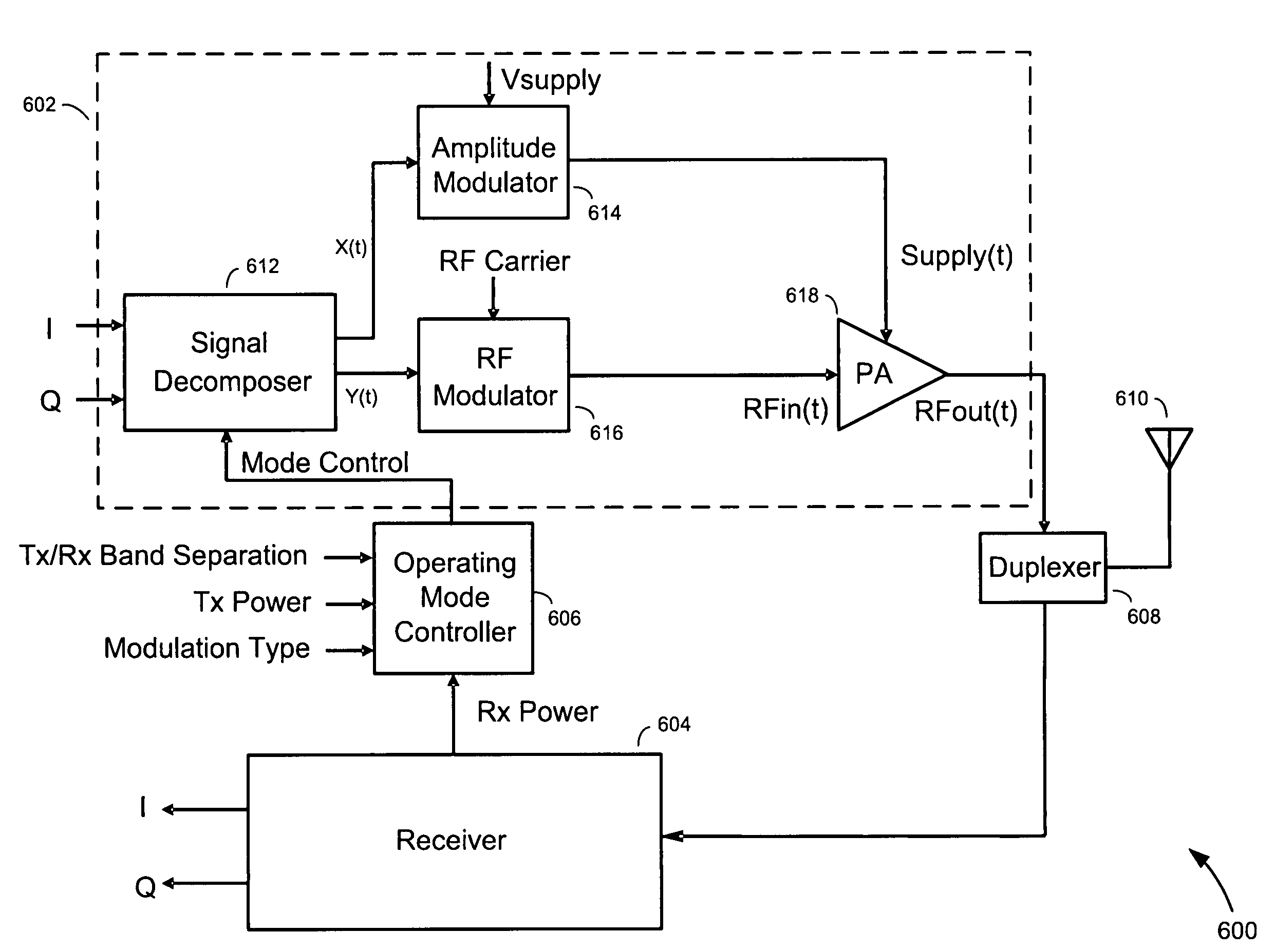
[0030]Referring to FIG. 6, there is shown a transceiver apparatus 600, according to an embodiment of the present invention. The transceiver apparatus 600 comprises a multi-mode transmitter 602, a receiver 604, an operating mode controller 606, a duplexer 608, and an antenna 610.

[0031]The multi-mode transmitter 602 includes a signal decomposer 612, an amplitude modulator 614 configured within a first modulation path, a radio frequency (RF) modulator 616 configured within a second modulation path, and a power amplifier (PA) 618. The amplitude modulator 614 operates to modulate a direct current (DC) power supply signal Vsupply according to amplitude information represented in a first modulation signal X(t) generated and provided by the signal decomposer 612. The resulting amplitude modulated power supply signal Supply(t) is coupled to the power supply input of the PA 618. Meanwhile, the RF modulator 616 operates to modulate an RF carrier signal according to angle (i.e., frequency or ph...


PUM


Abstract

Methods and apparatus for transmitting communications signals that are both power efficient and effective at avoiding or reducing transmitter-generated receive band noise. An exemplary transceiver apparatus includes a multi-mode transmitter that is configurable to operate in a plurality of operating modes (e.g., a polar mode, a quadrature mode and a hybrid mode), a receiver, and an operating mode controller. The operating mode controller is configured to control which operating mode the transmitter is to operate, depending on one or more of a transmit (Tx) power, receive (Rx) power, the Tx power relative to the Rx power, a level of frequency separation between a Tx frequency band and a Rx frequency band (Tx / Rx band separation), and modulation type employed by the transmitter.

Description

FIELD OF THE INVENTION[0001]The present invention relates to communications transmitters. More specifically, the present invention relates to methods and apparatus for transmitting communications signals that are both power efficient and effective at avoiding or reducing transmitter-generated receive band noise.BACKGROUND OF THE INVENTION[0002]Wireless communications devices include two essential components—a transmitter and a receiver. In mobile wireless communications devices, such as cellular handsets, the transmitter and receiver are combined into a single unit and share a common antenna. When combined in this manner, the transmitter and receiver are collectively referred to as a “transceiver.”[0003]Transceivers are generally categorized as being either “half-duplex” or “full-duplex”. In a half-duplex transceiver, only one of the transmitter and receiver is permitted to operate at any give time. In a full-duplex transceiver the transmitter and receiver operate simultaneously. To...

Claims


Application Information

Patent Timeline
Patent Type & Authority Patents(United States)
IPC IPC(8): H01Q11/12H04B1/04
CPCH04B1/0057H04B1/38H04B2001/045H03F1/02H03F3/24
Inventor TAKINAMI, KOJILIANG, PAUL CHENG-PO
Owner APPLE INC
Why Eureka
Try Eureka