Drip emitter with an independent non-drain valve

a drip emitter and non-drain valve technology, applied in the field of drip emitters, can solve the problems of increased water pressure in the area, clogging of the drip emitter, additional challenge of the irrigation system, etc., and achieve the effects of easy manufacturing and assembly of the unit, low cost, and large flow passages

Active Publication Date: 2012-01-17
RIVULIS PLASTRO LTD
View PDF10 Cites 47 Cited by
  • Summary
  • Abstract
  • Description
  • Claims
  • Application Information

AI Technical Summary

Benefits of technology

[0029]A drip emitter in accordance with a preferred embodiments of the invention enables the manufacturing and assembly of the unit with ease—as it is inherently simple, coupled with relatively low cost, as a consequence of the small number of components it is made of. In the preferred embodiments of the invention, the drip emitters comprises only one elastomer component—of which one portion is dedicated to serve as the seal of the non-drain valve and one more portion is implemented as the regulating membrane.
[0030]A drip emitter in accordance with another and additional preferred embodiment of the invention adopts and keeps the inherent advantages of the differential regulation principle (i.e., self rinsing or flushing) and enables forming its throttle means with relatively large flow passages, thus reducing the number of clogging phenomena occurrences.

Problems solved by technology

Irrigation systems utilizing drip emitters pose an additional challenge.
Since these contaminants are larger than this narrow passage, a clog is formed.
But this clog immediately causes an increase of the water pressure in the area in the vicinity preceding the clog location.
But, due to the sudden pressure increase upon clogging, the membrane would then tend to retreat a little.
Thus, exploiting the same membrane to accomplish two goals—to perform the regulation operation and to serve as a seal of the non-drain valve, was found to be associated with considerable difficulties that might even harm the unmistakably clear advantages of the differential regulation principle and impart constraints on advanced design of the throttle means in drip emitters.
As a consequence, the utilization of the same membrane for the two functions as suggested,—i.e. regulation and seal in the non-drain valve, does not provide an answer to the requirements of the agriculture community, that the non-drain valve would enable closing the drip emitter and prevent drainage through it, even at relatively high pressure values that prevail in the water supply conduit—three to seven (3-7) meter.
The ensuing drawback is that drip emitter as per this prior art is prone to malfunctions because a relatively narrow flow passage is formed in the non-drain valve.
A narrow flow passage that may be suffices for passing the required throughput but might lead to the danger of accumulating contaminants already at the non-drain valve location.
The ensuing drawback is that resorting to use two different elastomer components causes an increase of the manufacturing and assembling expenditures of the drip emitters (obviously—as an additional elastomer component is added).
Moreover, similarly to what was explained above when referring to Eckstein's patent U.S. Pat. No. 5,615,838, in the present case too, a drip emitter in accordance with this prior art is prone to the formation of a relatively narrow flow passage in the non-drain valve.
Such a narrow flow passage that may be suffices for passing the required water quantity throughput but might lead to the danger of accumulating contaminants already at the non-drain valve space.

Method used


Image

  • Drip emitter with an independent non-drain valve
  • Drip emitter with an independent non-drain valve
  • Drip emitter with an independent non-drain valve

Examples


Embodiment Construction

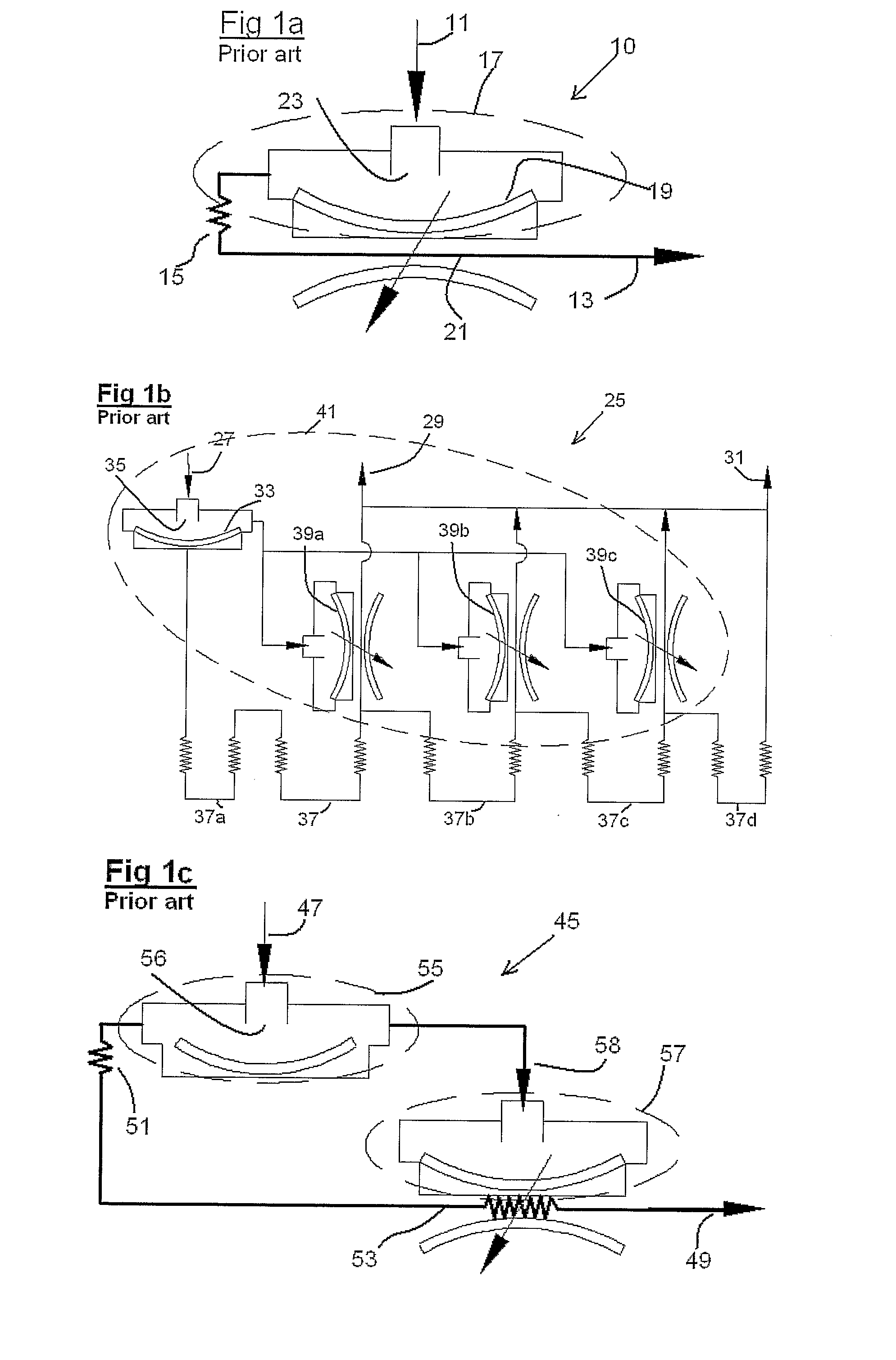
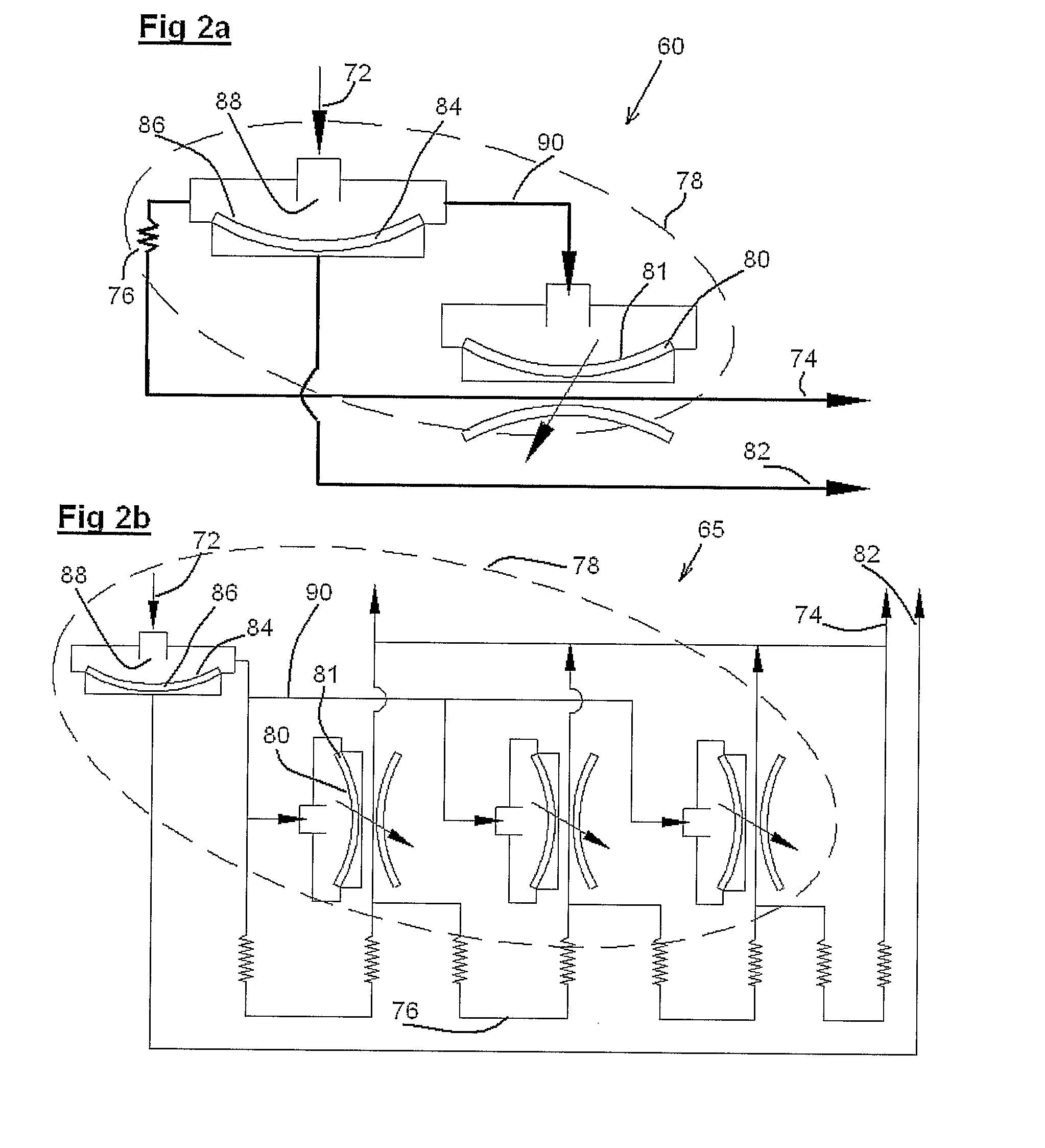
[0053]Referring to FIGS. 2a to 2c. These figures constitute schematic illustrations of examples of regulated drip emitters with an independent non-drain valve, in accordance with the present invention. Any professional in this field would be able to evaluate the constructional characteristic of the present invention, the method of its operation and the important differences between it and the prior art from comparing these figures to the schematic illustrations of examples of regulated drip emitters equipped with non-drain valves in accordance with the prior art, as this prior art was explained above, in the “Background of the Invention” chapter, while referring to FIGS. 1a to 1c.

[0054]A schematic view of a drip emitter 60 is presented in FIG. 2a. Drip emitter 60 is of the kind in which a regulating mechanism is implemented, one that increases or decreases the dimensions of the flow passage of the water, after the water passed and emerged from the throttle means, towards the water ...


PUM


Abstract

An elastomer membrane based, regulated drip emitter unit, equipped with a non-drip valve, wherein the drip emitter is characterized by that it includes an opening that is exposable to an approximate atmospheric pressure that prevails on the water outlet from the drip emitter; and an additional elastomer membrane portion that is strained and biased against the water inlet opening of the drip emitter for creating a seal with its one side for a non-drain valve and on its other (second) side it is connected to that atmospheric pressure prevailing opening, and wherein the elastomer membrane portion is movable towards that opening in order to open the water inlet opening for enabling a water flow passage from a water supply conduit to the drip emitter, and this from the specific instant that the force exerted by the water pressure prevailing in the water supply conduit on one side of that elastomer portion, overcomes the strain at which that portion was strained and biased against the water inlet opening, as well as the approximate atmospheric pressure that prevails on the other side of that elastomer portion.

Description

RELATED APPLICATION DATA[0001]This application is the U.S. national stage of PCT / IL2006 / 001207 filed on Oct. 19, 2006, which is based on and claims the benefit of Israeli Application No. 171482 filed on Oct. 19, 2005, the content of each of which is expressly incorporated herein in its entirety by reference hereto.FIELD OF THE INVENTION[0002]The invention, subject matter of this application, relates to the field of drip emitters that incorporate a regulating mechanism and a non-drip valve.BACKGROUND OF THE INVENTION[0003]Preliminary Remark—the invention presented herein after would be described in terms of applications referring to agricultural irrigation with water. However, any professional in this field would understand that the invention is not restricted solely to this field, but rather the invention is also applicable to drip emitters that are employed in other fields, such as, for example—wetting and flushing (rinsing) minerals with water or using various different liquids th...

Claims


Application Information

Patent Timeline
Patent Type & Authority Patents(United States)
IPC IPC(8): B05B15/00B05B1/34B05B1/30
CPCF16K23/00A01G25/023
Inventor LUTZKI, MOSHEEINAV, ZVIKA
Owner RIVULIS PLASTRO LTD
Why Eureka
Try Eureka