
Method and apparatus for suppressing adjacent channel interference and multipath propagation signals and radio receiver using said apparatus

a multi-path propagation and adjacent channel technology, applied in the direction of line-fault/interference reduction, transmission monitoring, baseband system details, etc., can solve the problems of adjacent channel interference in broadcast signals, disturbance and/or distortion in reception, and signal reflection, etc., to suppress the presence of multi-path propagation, the cost of production and achievement is considerably less

Active Publication Date: 2012-01-17
MICROELECTRONIC INNOVATIONS LLC
View PDF20 Cites 7 Cited by
  • Summary
  • Abstract
  • Description
  • Claims
  • Application Information

AI Technical Summary

Benefits of technology

[0029]One embodiment is a receiver with a simple structure and with a reduced number of components which is capable of reducing at the same time the overall cost of the receiver.
[0035]Due to the present invention, it is possible to obtain a method and an apparatus capable of suppressing the presence of multipath propagation by using simpler instructions with respect to the prior art.
[0036]Moreover, it is possible to obtain an apparatus capable of suppressing the presence of multipath propagation in order to reconstruct the originally transmitted signal free of multipath noise, employing a lower number of components and smaller-size memory elements.
[0037]A further advantageous feature is that of obtaining a radio receiver equipped with the apparatus for suppressing the presence of multipath propagation whose cost of production and achievement is considerably less with respect to the prior art radio receivers.
[0045]Due to the present invention, it is possible to obtain a method and an apparatus capable of detecting the adjacent channel interference in a modulated digital signal by using a simpler technique with respect to those employed at the state of the art, and suppressing or at least greatly reducing such adjacent channel interference in the modulated digital signal.
[0046]Moreover, it is possible to obtain an apparatus capable of detecting and suppressing or at least greatly reducing the adjacent channel interference in a modulated digital signal.

Problems solved by technology

Indeed, during their propagation the transmitted signals are subjected to reflections which are caused by objects present in the broadcasting zone.
Such system, even if certain advantageous features are present, nevertheless requires numerous circuit components and the implementation of specific software which is particular burdensome from the standpoint of computational complexity, with the consequence of having to employ high memory quantities.
The problem of adjacent channel interference in broadcast signals is known, particularly in AM / FM signals.
Adjacent channel interference is due to the presence of channels with high field intensity adjacent to the selected channel which one wishes to receive.
In the present case, the radio waves of the adjacent channel are found to interfere with the radio waves of the desired broadcast channel, causing disturbances and / or distortions in the reception of the desired channel signal by an AM / FM radio receiver.
Other techniques require high performance hardware circuitry with a consequent increase in the costs of the apparatus for detecting and suppressing the adjacent channel interference, and consequently, in the overall cost of the AM / FM radio receiver in which such apparatus is incorporated.
Moreover, the methods and apparatuses therein described require a conversion of the received signal from the frequency of the selected carrier to an intermediate frequency IF, and hence the use of external mixers and filters for the intermediate frequency whose cost substantially impacts on the overall cost of the receiver.

Method used


Image

  • Method and apparatus for suppressing adjacent channel interference and multipath propagation signals and radio receiver using said apparatus
  • Method and apparatus for suppressing adjacent channel interference and multipath propagation signals and radio receiver using said apparatus
  • Method and apparatus for suppressing adjacent channel interference and multipath propagation signals and radio receiver using said apparatus

Examples


Embodiment Construction

Suppressing Multipath Propagation

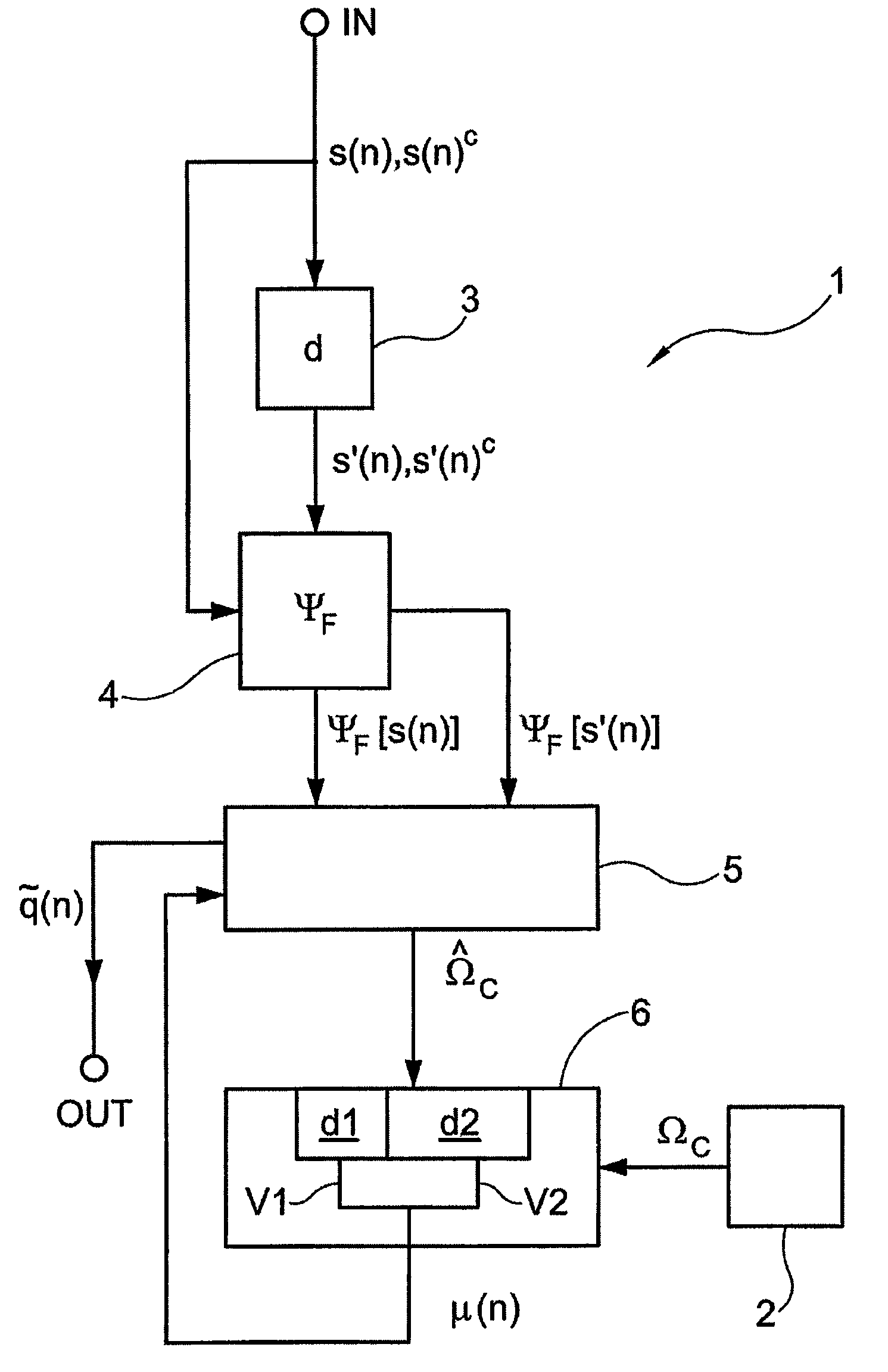
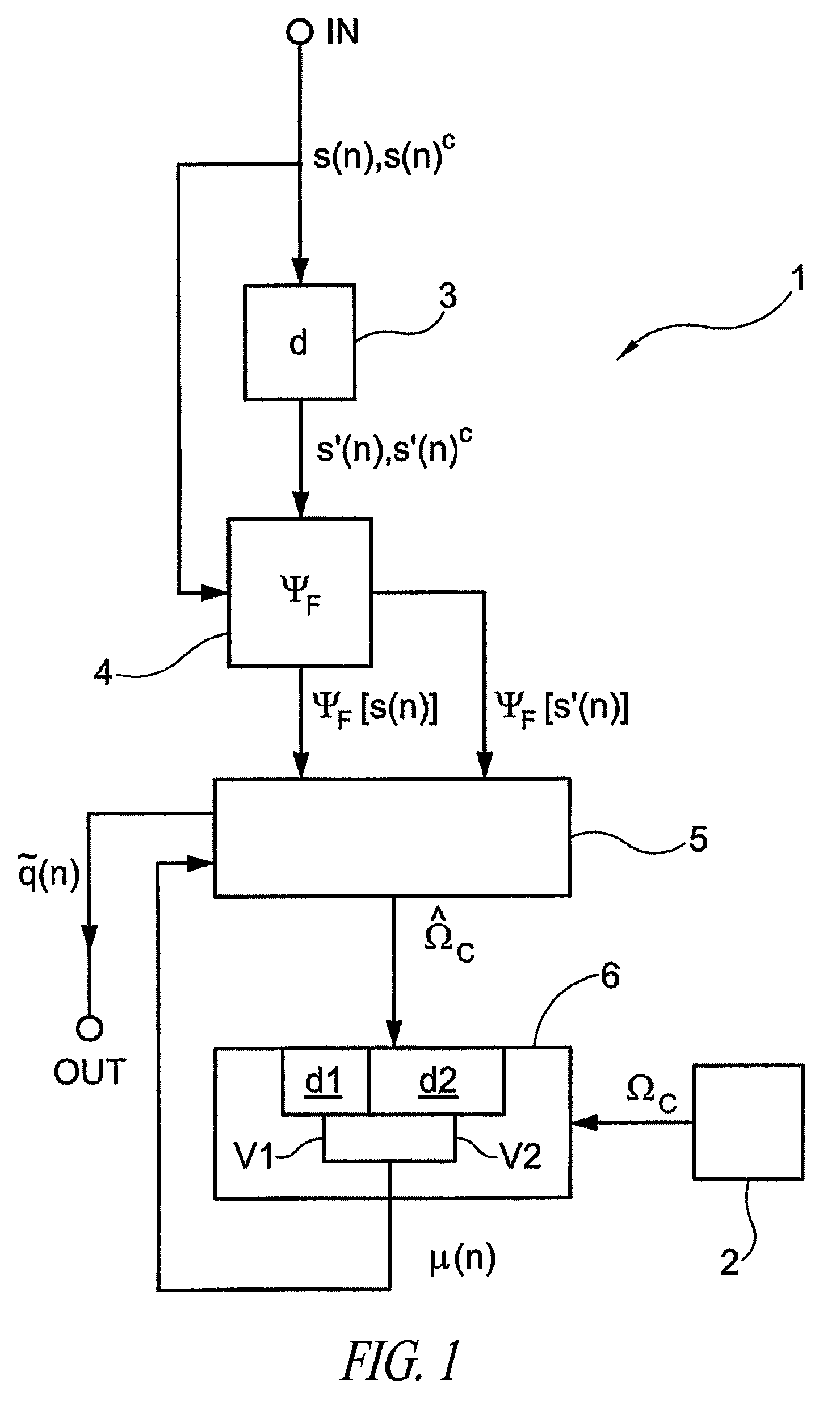
[0055]With reference to FIG. 1, in which the explanatory diagram of the method and apparatus 1 for suppressing the presence of multipath propagation in a received signal s(n), s(n)c is shown, it is noted that such apparatus 1 comprises an input terminal IN and an output terminal OUT, which are respectively associable to a front end and a back end of a receiver (not illustrated in the figure), as described in more detail below.

[0056]It should be indicated that in such FIG. 1, only the elements necessary for understanding the operation and achievement of the embodiment are illustrated. The person skilled in the art will be capable of understanding which other elements are necessary, how to design, implement and connect them with the other elements in order to make a complete diagram of a receiver.

[0057]Before proceeding with the description, it should be underlined that the signal s(n), s(n)c received from the receiver is an FM modulated digital signal...


PUM


Abstract

A method detects multipath propagation in a modulated digital signal. The method provides a first value of channel frequency, representing the modulated digital signal free of multipath propagation, providing a second value of said channel frequency, representing the modulated digital signal with multipath propagation, and comparing the first and second values. A method detects adjacent channel interference in a modulated digital signal by comparing first and second values of a characteristic parameter of the digital signal, respectively representing the digital signal free of adjacent channel interference and the digital signal affected by adjacent channel interference. In particular, the method obtains a derivative signal, applies a non-linear Teager-Kaiser function to the digital signal and the derivative signal for generating first and second signals respectively representing energy content of the digital signal and energy content of the derivative signal, and processes the first and second signals for generating the second value.

Description

CROSS-REFERENCE TO RELATED APPLICATION[0001]This application claims the benefit under 35 U.S.C. §120 of European Patent Application No. 06425683.7, filed on Oct. 6, 2006, and European Patent Application No. 06425686.0, filed on Oct. 6, 2006, which are incorporated herein by reference in their entireties.BACKGROUND[0002]1. Technical Field[0003]The present invention refers to a method and an apparatus for suppressing the presence of multipath propagation in a broadcast signal.[0004]The present invention moreover refers to a radio receiver using said apparatus.[0005]The present invention refers to a method and an apparatus for detecting adjacent channel interference in a modulated digital signal.[0006]The present invention moreover refers to a method and apparatus for suppressing adjacent channel interference in a modulated digital signal.[0007]The present invention also refers to a radio receiver using said apparatus.[0008]2. Description of the Related Art[0009]In terrestrial broadcas...

Claims


Application Information

Patent Timeline
Patent Type & Authority Patents(United States)
IPC IPC(8): H04B3/46H04B15/00H04L25/03
CPCH04L25/0202
Inventor ADDUCI, FRANCESCO
Owner MICROELECTRONIC INNOVATIONS LLC
Learn More