Liquid discharging head, liquid discharging apparatus, and bubble removing method for the liquid discharging apparatus

a liquid discharging apparatus and liquid discharging head technology, applied in printing and other directions, can solve the problems of insufficient removal of bubbles, and difficulty in line printing, and achieve stable ink supply, smooth removal of bubbles, and stable ink supply

Inactive Publication Date: 2012-01-24
SONY CORP
View PDF3 Cites 8 Cited by
  • Summary
  • Abstract
  • Description
  • Claims
  • Application Information

AI Technical Summary

Benefits of technology

[0027]Therefore, in the line printer 200 of the series connection type, ink is circulated in series by driving the pump 11, as shown by the arrows in FIG. 9, so that bubbles are removed from the ink. That is, bubbles contained in the ink in the common passage of the buffer tank 221 are transferred to the subtank 12 via the common passage of the buffer tank 231, and are removed by being released into the atmosphere. Even when ink in the common passage of the buffer tank 231 contains bubbles, the bubbles are transferred to the subtank 12 and are then removed. Even when the bubbles in the ink form an air accumulation, the ink in the common passage of the buffer tank 221 and the ink in the common passage of the buffer tank 231 similarly circulate. This allows smooth removal of bubbles in the line head 210.
[0033]Accordingly, it is desirable to stably supply liquid (ink) to each common passage for the liquid and to smoothly remove bubbles from the liquid in the common passage.
[0038]According to the embodiments of the present invention, the common passage members are connected in parallel by opening the opening-closing valve. Therefore, when the liquid in the liquid chambers is discharged by driving the energy generating elements in the head chip, stable ink supply can be achieved by transferring the liquid by driving the transfer means with the opening-closing valve open. Further, the common passage members are connected in series by closing the opening-closing valve. Therefore, bubbles can be smoothly removed from the liquid in the common passages of all the common passage members by transferring the liquid by driving the transfer means with the opening-closing valve closed. As a result, it is possible to achieve both stable ink supply and smooth removal of bubbles.

Problems solved by technology

Unfortunately, it is difficult for the line printer disclosed in the above-described publication to sufficiently remove bubbles from the ink.
For this reason, in the parallel connection method, essential ink, which contains a lot of bubbles, is not sufficiently circulated, and as a result, removal of bubbles is insufficient.

Method used


Image

  • Liquid discharging head, liquid discharging apparatus, and bubble removing method for the liquid discharging apparatus
  • Liquid discharging head, liquid discharging apparatus, and bubble removing method for the liquid discharging apparatus
  • Liquid discharging head, liquid discharging apparatus, and bubble removing method for the liquid discharging apparatus

Examples


Embodiment Construction

[0048]An embodiment of the present invention will be described below with reference to the drawings.

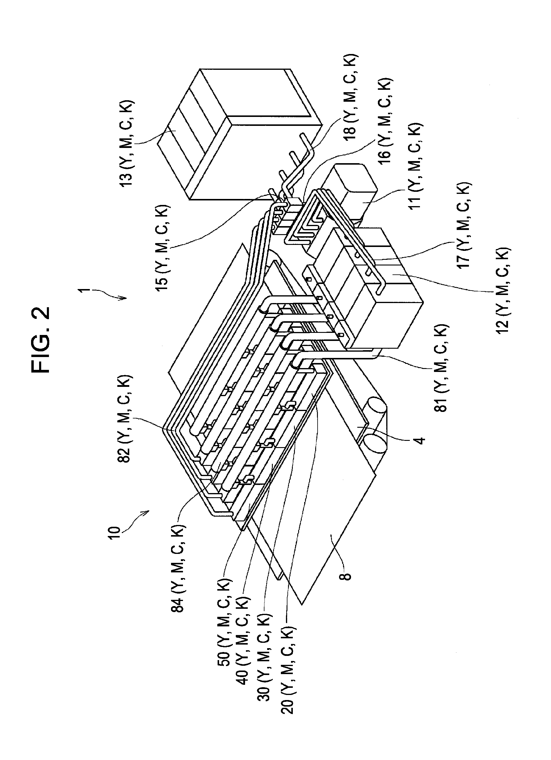
[0049]In the following embodiment, a color inkjet printer (line printer 1) that discharges inks (liquids) of four colors, Y (yellow), M (magenta), C (cyan), and K (black) will be described as an example of a liquid discharging apparatus according to the present invention. A line head 10 used in the line printer 1 corresponds to a liquid discharging head in the present invention.

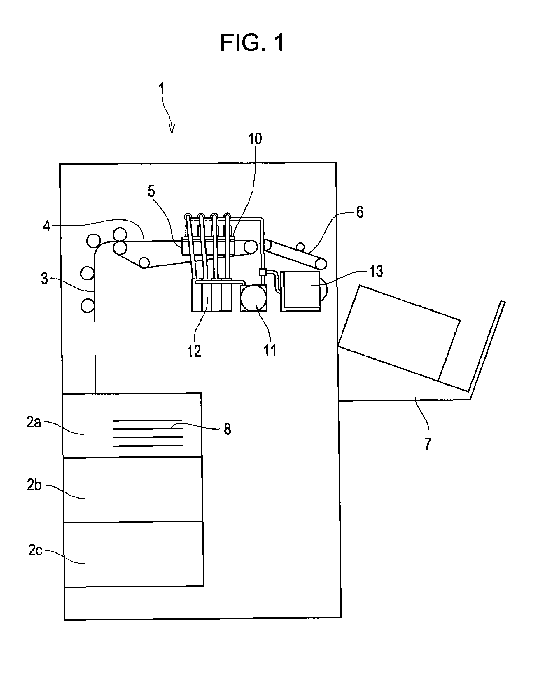
[0050]FIG. 1 is a general front view of the line printer 1 according to the embodiment.

[0051]As shown in FIG. 1, the line printer 1 includes a plurality of sheet trays 2a, 2b, and 2c, a conveying unit 3 that conveys each recording sheet 8 selectively supplied from the sheet trays 2a, 2b, and 2c in accordance with the print size, a print table 4 on which the recording sheet 8 faces the line head 10, a maintenance unit 5 that covers an ink discharging surface of the line head 10 in a non-printing state, an output...


PUM


Abstract

A liquid discharging head includes a head chip including a plurality of energy generating elements configured to discharge liquid, and liquid chambers provided around the energy generating elements, and a common passage member configured to define a common passage communicating with all the liquid chambers. Liquid is discharged from the liquid chambers by driving the energy generating elements so as to apply a discharging force to the liquid. N-number of common passage members (N≧2) are provided, and each includes an inlet for supplying the liquid to the common passage and an outlet for ejecting the liquid from the common passage. The inlet of the first common passage member is connected to a liquid supply member. The inlet of the N-th common passage member is connected to the liquid supply member via an opening-closing valve and to the outlet of the (N−1)-th common passage member.

Description

CROSS REFERENCES TO RELATED APPLICATIONS[0001]The present invention contains subject matter related to Japanese Patent Application JP 2007-090862 filed in the Japanese Patent Office on Mar. 30, 2007, the entire contents of which are incorporated herein by reference.BACKGROUND OF THE INVENTION[0002]1. Field of the Invention[0003]The present invention relates to a liquid discharging head and a liquid discharging apparatus which include a plurality of common passage members that define common passages communicating with all liquid chambers in head chips and which discharge liquid from the liquid chambers by driving energy generating elements of the head chips so as to apply a discharging force to the liquid in the liquid chambers, and to a bubble removing method for the liquid discharging apparatus. More particularly, the present invention relates to a technique of stably supplying liquid to the common passages of the common passage members and of smoothly removing bubbles from the liq...

Claims


Application Information

Patent Timeline
Patent Type & Authority Patents(United States)
IPC IPC(8): B41J2/18
CPCB41J2/175B41J2/515
Inventor HIRASHIMA, SHIGEYOSHI
Owner SONY CORP
Why Eureka
Try Eureka