Element of belt for continuously variable transmission and belt for continuously variable transmission

a technology of continuously variable transmission and belt, which is applied in the direction of driving belts, belts/chains/gearrings, v-belts, etc., can solve the problems of not revealing a countermeasure against such bending loads to improve strength or durability, and it is difficult to relax stress concentration, so as to achieve the effect of reducing stress concentration and enhancing strength and durability of the neck portion

Active Publication Date: 2012-01-24
TOYOTA JIDOSHA KK
View PDF19 Cites 3 Cited by
  • Summary
  • Abstract
  • Description
  • Claims
  • Application Information

AI Technical Summary

Benefits of technology

[0007]The present invention has been conceived noting the technical problems thus far described, and its object is to provide a belt for a continuously variable transmission, and to improve a strength or durability of an element used in the belt without enlarging the element. More specifically, an objective of the present invention is to enhance a strength or durability of the element and the belt using the element by relaxing stress concentration on a base portion of a neck portion of the element.
[0010]According to the element of the present invention and the driving belt using the same, the width end portion of the ring fastening the elements is thus inserted into a space between the saddle face and the stopper portion. Therefore, the elements can be prevented from moving relatively toward the outer circumferential side of the ring. Moreover, even in case a load is applied to the element in a direction to move the element relatively toward the inner circumferential side of the ring, the stopper portion is contacted with the ring to prevent such relative movement of the element. In this case, a load is generated to push the stopper portion in the direction opposite to the saddle face, and a resultant bending load is applied to the neck portion. Especially, the maximum bending load is applied to the base portion of the neck portion, that is, to the corner between the neck portion and the saddle face. In addition, a load is applied to both lateral faces of the element in the traveling direction of the belt as a result of transmitting the torque between the pulleys and the element, and a load in the opposite direction is applied to the saddle face. Consequently, the element is subjected to a bending stress in the thickness direction thereof, and especially, such stress is applied significantly to the border between the saddle face and the neck portion at which the cross-sectional area is changed. Therefore, as described, the recessed portion is formed on the aforementioned corner at which the bending stress is applied. Specifically, the curvature radius of the inner face of the recessed portion is relatively larger at the portion extending into the side face of the neck portion, and relatively smaller at the portion extending thereto, that is, at the saddle face side. For this reason, stress concentration factor is reduced relatively at the base portion of the neck portion so that the strength and the durability of the neck portion can be enhanced without thickening the neck portion itself or without widening the width of the neck portion.

Problems solved by technology

Thus, according to the structure taught by Japanese Patent Laid-Open No. 2002-39280, it would be difficult to relax the stress concentration if the curvature radius of the recess is reduced for the purpose of avoiding enlargement of the element.
However, Japanese Patent Laid-Open No. 2002-39280 fails to disclose a countermeasure against such bending load to improve strength or durability of the element.

Method used


Image

  • Element of belt for continuously variable transmission and belt for continuously variable transmission
  • Element of belt for continuously variable transmission and belt for continuously variable transmission
  • Element of belt for continuously variable transmission and belt for continuously variable transmission

Examples


Embodiment Construction

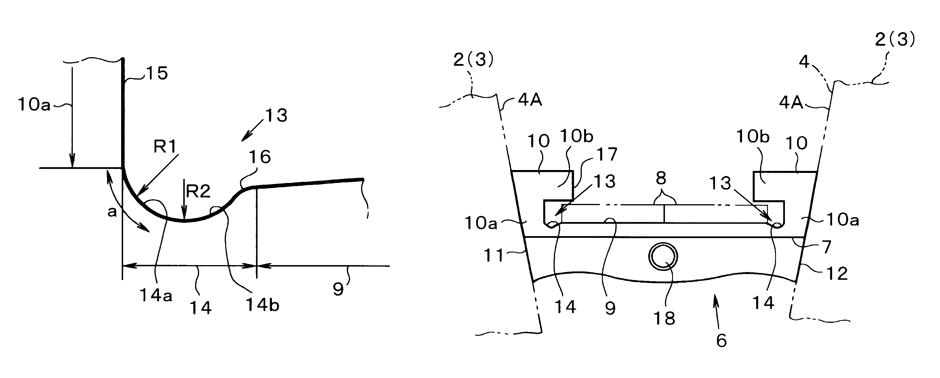
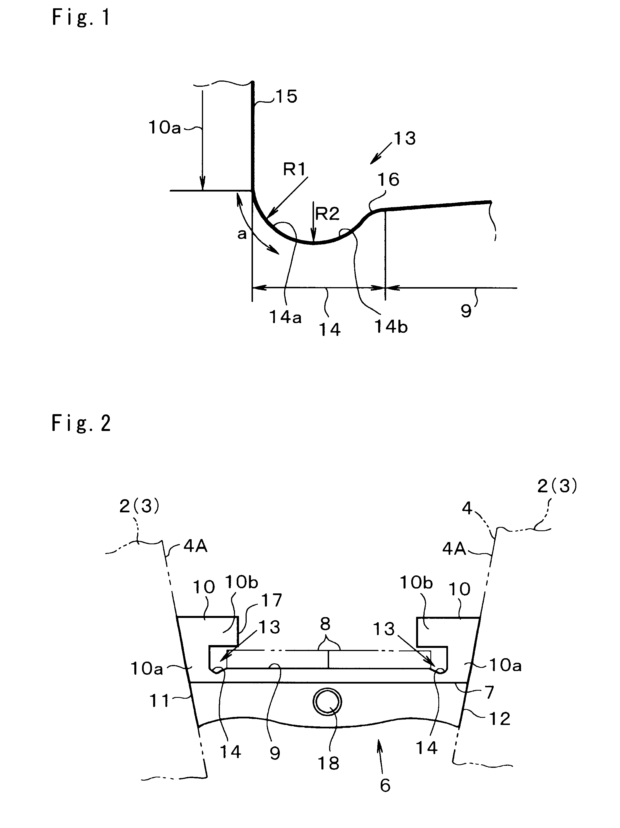
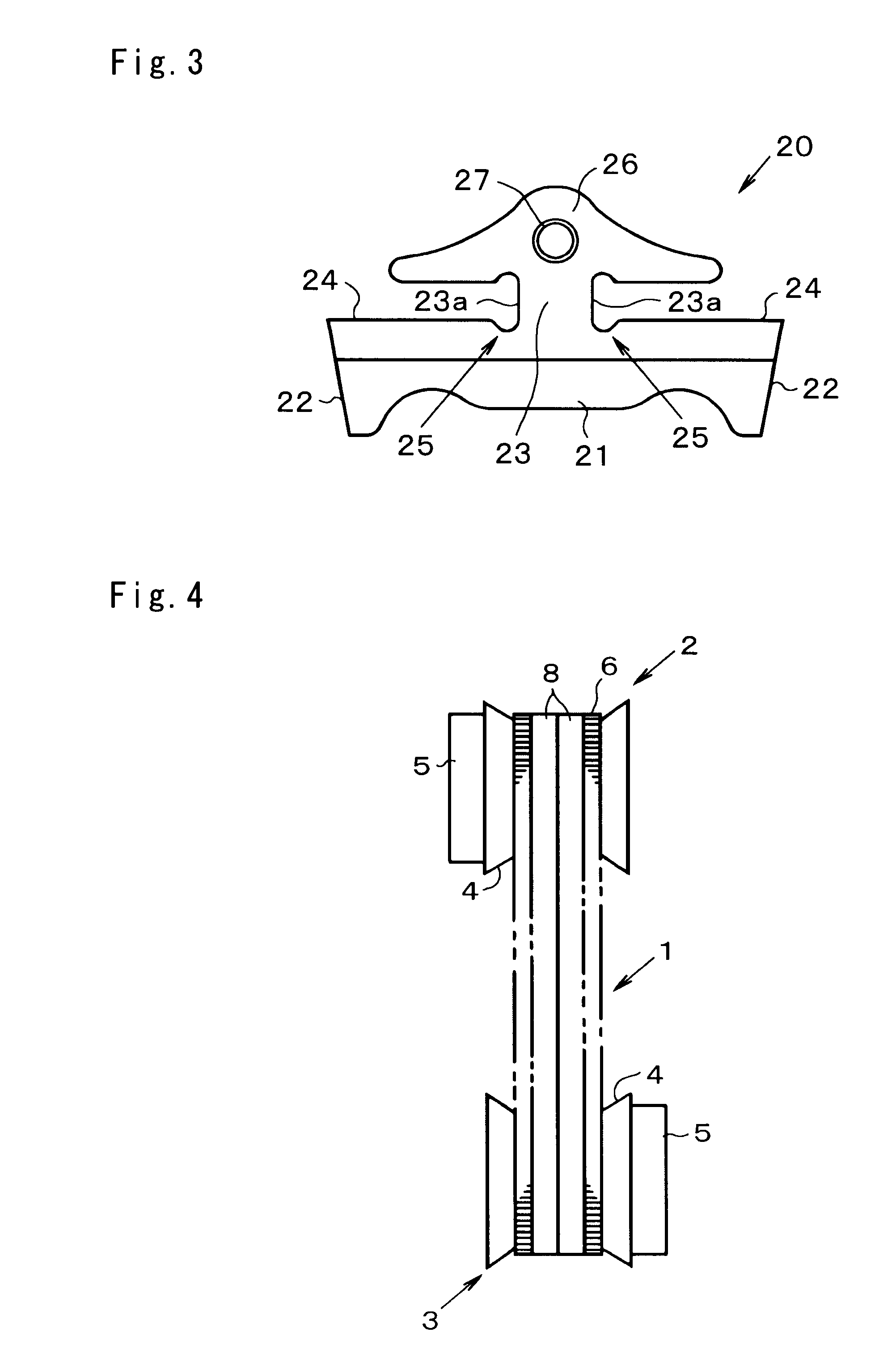
[0015]Next, examples of the present invention will be explained hereinafter. A belt to which the present invention is applied is adapted to be used in a continuously variable transmission. Specifically, a groove whose cross-sectional shape is V-shaped is formed on an outer circumference of the pulley of the continuously variable transmission, and the belt is applied to the groove of the pulley for the purpose of transmitting torque by a frictional force between the belt and pulleys. For example, as schematically shown in FIG. 4, a belt 1 is applied to a drive pulley 2 and a driven pulley 3 of the continuously variable transmission. Each pulley 2 and 3 comprises a pair of fixed sheave and movable sheave individually having a tapered face and being opposed to each other. Therefore, V-shaped groove 4 is formed between those sheaves, and a width of the groove 4 is varied by reciprocating the movable sheave by an actuator 5 such as hydraulic cylinder.

[0016]The belt 1 thus used is formed ...


PUM


Abstract

A belt for a continuously variable transmission and elements used in the belt. The elements include a stopper portion formed integrally with a neck portion erected upwardly from a saddle face to hold a width end portion of the ring. The elements are juxtaposed annularly in a same orientation and fastened by rings disposed on a saddle face of the element thereby forming a belt for a continuously variable transmission. A recessed portion is formed by depressing the saddle face at a corner between a side face of the neck portion and the saddle face; and an inner face of the recessed portion includes a first inner face extending smoothly into the side face of the neck portion and having a relatively larger curvature radius, and a second inner face extending smoothly into the first inner face and having a relatively smaller curvature radius.

Description

TECHNICAL FIELD[0001]This invention relates to a belt to be applied to grooves of pulleys to transmit a torque, and to an element to be used to form the belt.BACKGROUND ART[0002]A belt formed by juxtaposing a plurality of metal pieces called an “element” or a “block” in a circular manner, and by fastening the juxtaposing metal pieces by a metal belt member called a “ring” or a “hoop” is known in the prior art to be used in a continuously variable transmission. The belt of this kind is adapted to transmit the torque by a pushing force among the metal pieces thus juxtaposed to be contacted to one another. Specifically, the metal pieces existing in the groove of a drive pulley are sequentially pushed out of the groove by a rotation of the pulley while pushing the metal pieces in front of those metal pieces. The metal pieces thus being pushed forward are eventually entered into a groove of a driven pulley. As a result, the torque of the drive pulley is transmitted to the driven pulley b...

Claims


Application Information

Patent Timeline
Patent Type & Authority Patents(United States)
IPC IPC(8): F16G1/22
CPCF16G5/16
Inventor NISHIMI, HIDEYUKIKUWABARA, SHINYA
Owner TOYOTA JIDOSHA KK
Why Eureka
Try Eureka