Optically gated MEMS switch

a micro-electromechanical system and switch technology, applied in the field of power switching, can solve the problems of unintentional turn-on or unintentional turn-off of the gate drive, electromagnetic radiation from high frequency current flowing, and the operational performance of the gate drive is degraded

Inactive Publication Date: 2012-01-24
GENERAL ELECTRIC CO
View PDF6 Cites 17 Cited by
  • Summary
  • Abstract
  • Description
  • Claims
  • Application Information

AI Technical Summary

Problems solved by technology

A drawback with this design is that electromagnetic interference (EMI) can degrade operational performance of the gate drive by inducing undesired voltages and / or currents in the conductor.
This condition can create two types of problems: 1) unintentional turn-on or unintentional turn-off of the gate drive, and 2) electromagnetic radiation from high frequency currents flowing down the wires.

Method used


Image

  • Optically gated MEMS switch
  • Optically gated MEMS switch
  • Optically gated MEMS switch

Examples


Embodiment Construction

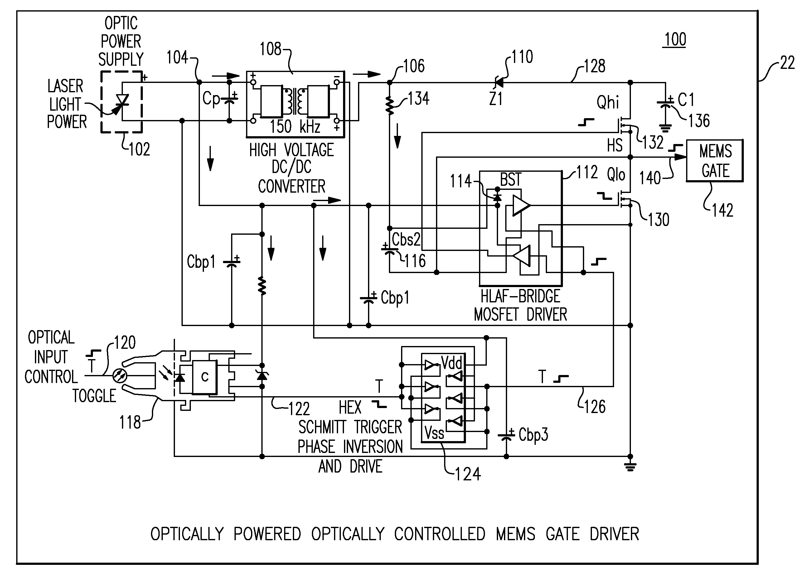
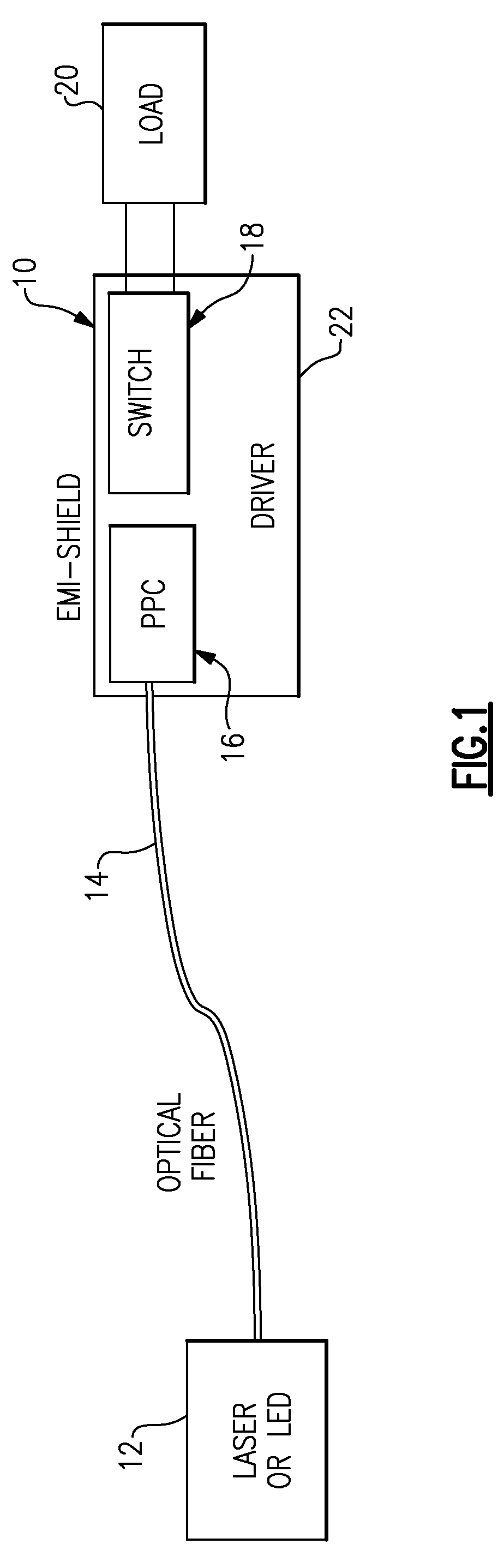
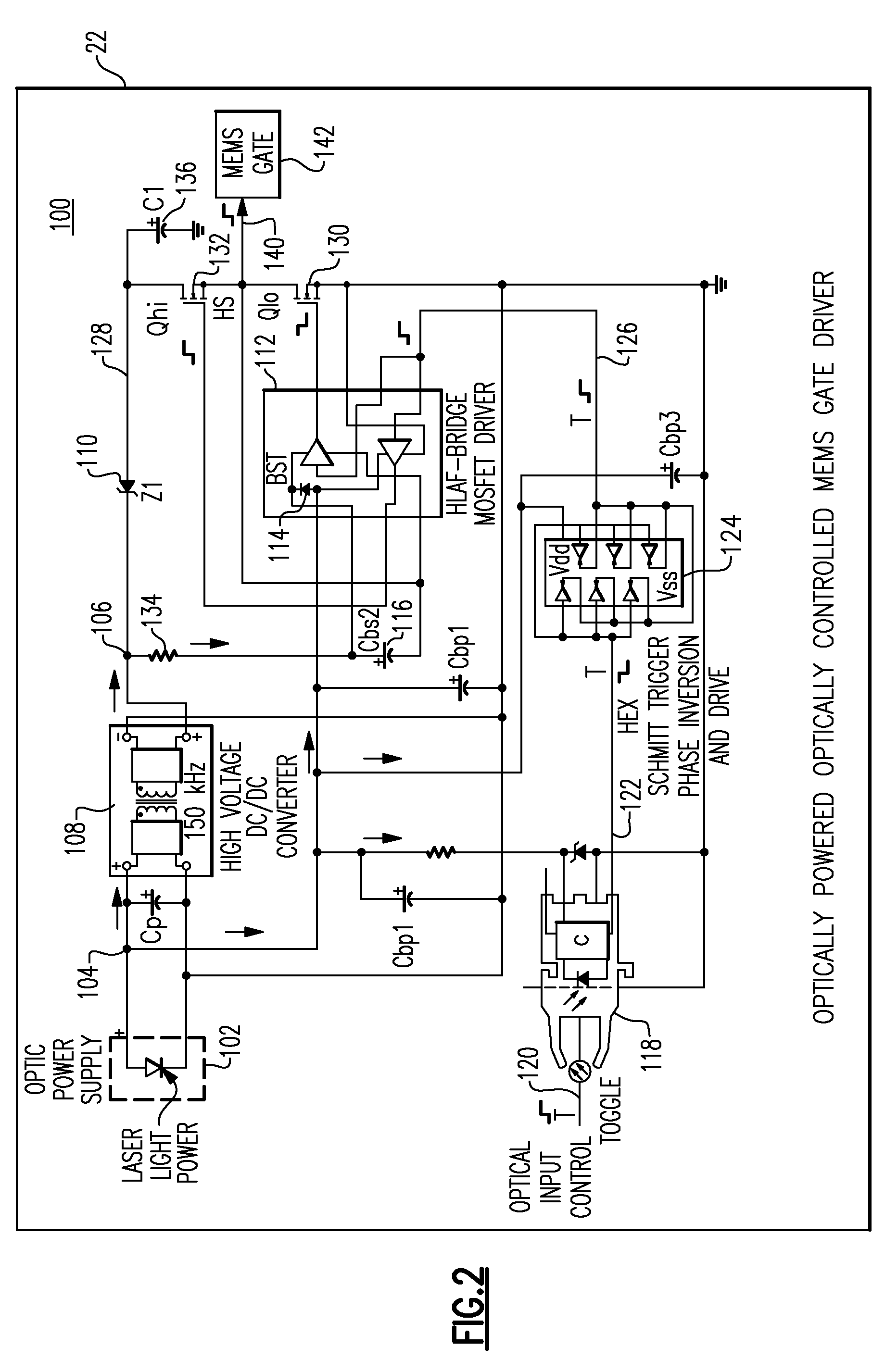
[0015]Referring to FIG. 1, a high level system diagram illustrating an optically powered and optically controlled high voltage power switch gate driver 10 in accordance with an exemplary embodiment is shown. The gate driver 10 includes a photovoltaic converter 16 and a high voltage switching circuit 18 comprising a DC to DC converter described in further detail below, and further comprising an electrical circuit, also described in more detail below.

[0016]A light source 12 comprising, for example, a laser light source is provided to generate a beam for propagation through a fiber optic cable 14 in order to control operation of gate driver 10. The light source 12 is optically coupled to the photovoltaic converter 16 through fiber optic cable 14. It should be noted that in an alternative embodiment, fiber optic cable 14 can contain more than one optical fiber thereby allowing a plurality of light beams to travel through one fiber optic cable.

[0017]The photovoltaic converter 16 is provi...


PUM


Abstract

An optically powered MEMS gate driver includes a photovoltaic converter configured to receive a light signal from a light source and output a DC supply voltage for a MEMS gate driver in response thereto. The MEMS gate driver further includes a DC to DC converter electrically coupled to the photovoltaic converter and configured to output a line level DC voltage in response to the DC supply voltage. An electrical circuit, also included as a portion of the MEMS gate driver is electrically coupled to both the photovoltaic converter and the DC to DC converter is configured to receive the supply voltage and the line level voltage and to output a line level drive signal in response thereto. The optically powered MEMS gate driver is self-contained within a common EMI enclosure thus providing isolation between the gate driver and command signal electronics.

Description

BACKGROUND[0001]The invention relates generally to power switching, and more particularly to an electrically isolated microelectromechanical system (MEMS) power switch gate driver using optical power and gate drive signal delivery.[0002]Electrical gate drives have been developed for controlling semiconductor switches used for energizing a load. The gate drive is electrically coupled to an external voltage source via at least two electrical conductors. A drawback with this design is that electromagnetic interference (EMI) can degrade operational performance of the gate drive by inducing undesired voltages and / or currents in the conductor. This condition can create two types of problems: 1) unintentional turn-on or unintentional turn-off of the gate drive, and 2) electromagnetic radiation from high frequency currents flowing down the wires.[0003]A need therefore exists for an improved gate drive mechanism that can be optically powered and controlled and that reduces and / or eliminates ...

Claims


Application Information

Patent Timeline
Patent Type & Authority Patents(United States)
IPC IPC(8): G01J1/44H01J40/14
CPCH03K17/941H01H59/0009
Inventor KOSTE, GLEN PETERO'BRIEN, KATHLEEN ANNSUBRAMANIAN, KANAKASABAPATHIPARK, JOHN NORTON
Owner GENERAL ELECTRIC CO
Why Eureka
Try Eureka