Electrical direct drive for a roller

a direct drive and electric technology, applied in the direction of magnetic circuit rotating parts, mechanical energy handling, magnetic circuit shape/form/construction, etc., can solve the problems of high development cost of special motors, financial cost and time spent in the replacement of damaged gearboxes, etc., to avoid the cost of maintenance of a gearbox, avoid the effect of mechanical oscillation on the roller, and avoid the effect of development cos

Inactive Publication Date: 2012-01-24
SIEMENS AG
View PDF11 Cites 10 Cited by
  • Summary
  • Abstract
  • Description
  • Claims
  • Application Information

AI Technical Summary

Benefits of technology

[0011]A disk-type motor allows variable and precise matching to the torque required for the respective size or power level of the roller or of the production machine. Furthermore, the drive can easily be matched to the available physical space. The variable form of the torque to be emitted can be achieved in various ways with the disk-type motor.
[0012]The secondary part preferably may have a plurality of curved or straight secondary part elements. In this case, the secondary part can be designed such that a different number of secondary part elements can be arranged on one basic disk. In this case, a greater or lesser number of secondary part elements may be arranged, depending on the required power. However, the secondary part can also be designed such that the secondary part elements as a whole establish the disk. In this case, the maximum number of secondary part elements can be arranged to form a closed disk, in particular a closed ring, by means of the secondary part elements. Components of standard linear motors can advantageously be used as secondary part elements. This allows a secondary part to be produced easily and at low cost.
[0014]The primary part, which is in the form of a disk, likewise may have a plurality of curved or straight primary part elements, with each primary part element having a single-phase or polyphase winding. The primary part elements may be arranged at a specific distance and angle from one another in an annular or circular shape on a base plate. A greater or lesser number of primary part elements may be arranged depending on the desired power density and desired torque. Each primary part may preferably have a polyphase, in particular three-phase, winding for connection to a three-phase power supply system. The use of straight primary part elements allows advantageously the use of conventional primary parts of standard linear motors, which cost little and a primary part can be produced easily. Curved primary part elements on the other hand offer the advantage that a ring structure or a circular structure can be simulated better.
[0016]A disk-type motor offers the advantage that the torque and the power density of the disk-type motor can easily be variably adjusted. On the one hand, the air gap between the secondary part and the primary part, which runs at a right angle to the driven roller, may hereby be formed with a different width. If the air gap is very narrow or small, a greater power and a higher torque can be transmitted. The wider the air gap between the primary part and the secondary part, the less the torque which is transmitted to the roller.
[0020]The use of a disk-type motor in a continuous press for wood materials, or in other production machines, results in advantages over previously used motor-gearbox solutions. Simple matching to the required torque of the production machine is possible in which case, in particular, high-precision matching of the disk-type motor to the required torque can be achieved. Furthermore, a disk-type motor occupies a small area or space, in which case the geometry of the disk-type motor can be optimally matched to the spatial installation conditions of the roller. The described concept also allows a modular design of the direct drive thus avoiding development costs for special motors, which are manufactured specifically geometrically and in terms of power, in the area of direct drive technology. This avoids the costs for maintenance of a gearbox, and avoids mechanical oscillations on the roller resulting from the gearbox. The fitting, the removal and configuration of the drives on the roller of the continuous press are simplified.

Problems solved by technology

Drive concepts such as these incur high development costs for special motors which are manufactured specifically from the geometric and power point of view, in the area of direct drive technology and technical complexity, financial cost and time spent in replacement of damaged gearboxes.

Method used


Image

  • Electrical direct drive for a roller
  • Electrical direct drive for a roller
  • Electrical direct drive for a roller

Examples


Embodiment Construction

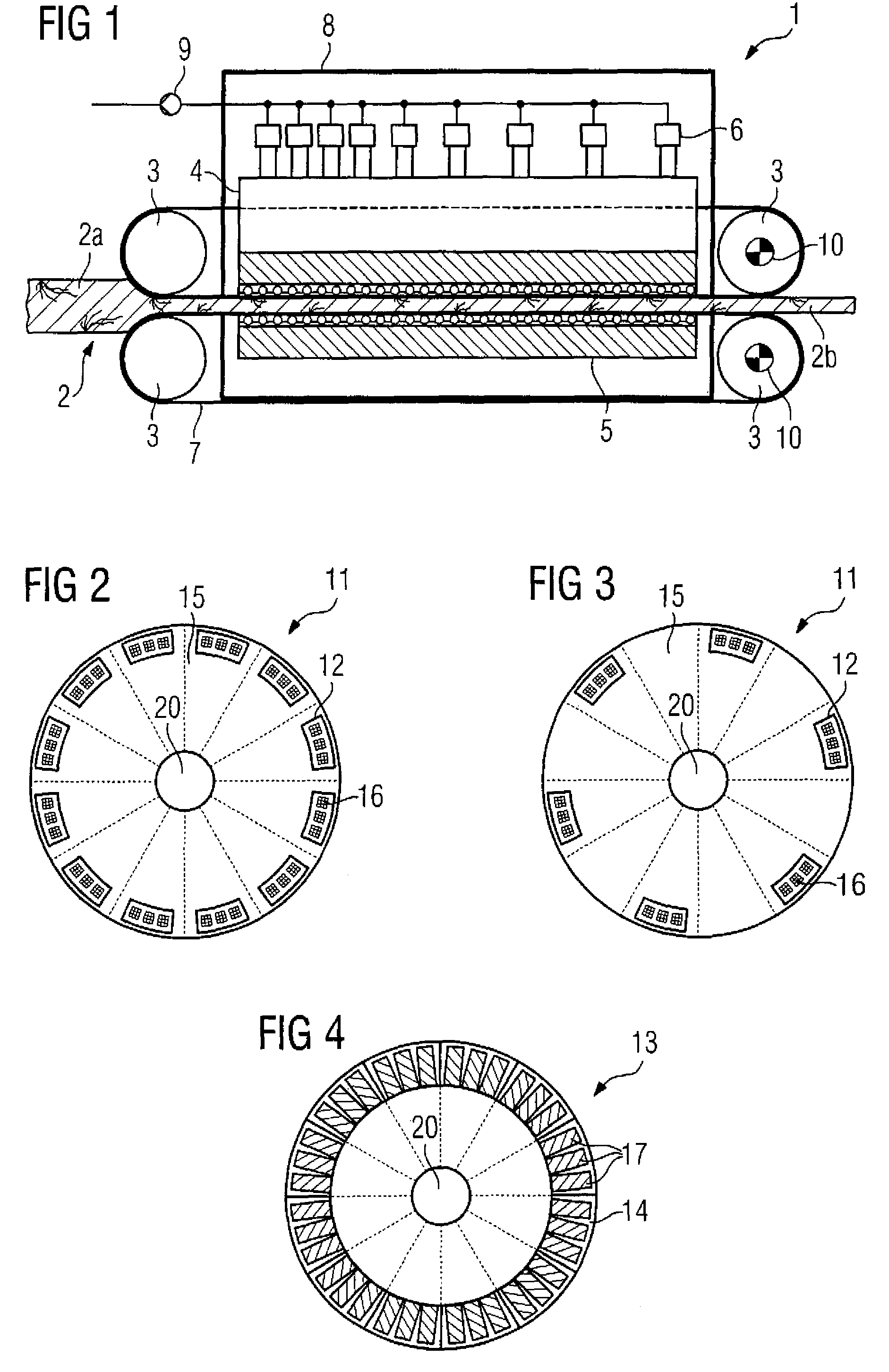
[0029]Throughout all the figures, same or corresponding elements may generally be indicated by same reference numerals. These depicted embodiments are to be understood as illustrative of the invention and not as limiting in any way. It should also be understood that the figures are not necessarily to scale and that the embodiments are sometimes illustrated by graphic symbols, phantom lines, diagrammatic representations and fragmentary views. In certain instances, details which are not necessary for an understanding of the present invention or which render other details difficult to perceive may have been omitted.

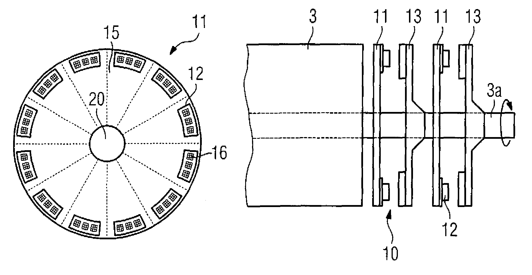
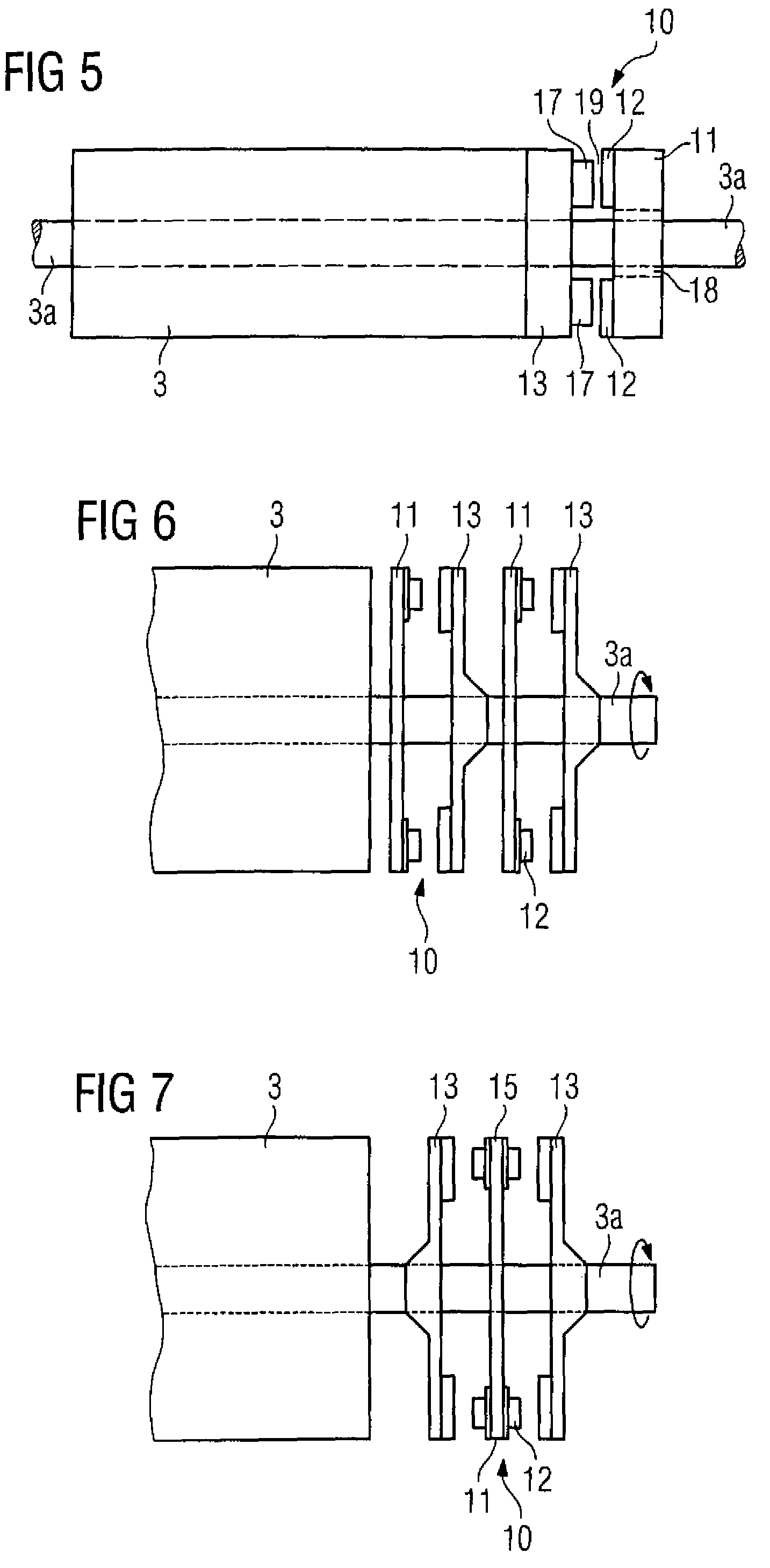
[0030]Turning now to the drawing, and in particular to FIG. 1, there is shown a schematic illustration of a production machine, generally designated by reference numeral 1 and constructed as a continuous press for wood materials. The production machine 1 has four rollers 3 which operate by continuous or step-by-step pressure forming of the rolled item 2. The rolled item is, ...


PUM


Abstract

An electrical roller drive which can be connected to a roller includes a disk-type motor with a secondary part in the form of a disk and with a primary part in the form of a disk.

Description

CROSS-REFERENCES TO RELATED APPLICATIONS[0001]This application claims the priority of European Patent Application, Serial No. EP 07022398, filed Nov. 19, 2007, pursuant to 35 U.S.C. 119(a)-(d), the content of which is incorporated herein by reference in its entirety as if fully set forth herein.BACKGROUND OF THE INVENTION[0002]The present invention relates to an electrical roller drive, which can be connected to a roller.[0003]Nothing in the following discussion of the state of the art is to be construed as an admission of prior art.[0004]Direct drives with high torques and total power levels at low rotation speeds are required to drive a roller in a production machine, for example a continuous press for wood materials. Currently, inter alia, it is desirable to change over in as simple a form as possible from a present drive variant (drive and gearbox) to direct drive technology. A solution is required for this purpose by means of which the given power range of the production machin...

Claims


Application Information

Patent Timeline
Patent Type & Authority Patents(United States)
IPC IPC(8): H02K1/22
CPCH02K7/14H02K21/24
Inventor HOFFMANN, HOLGERSCHIELE, STEFANSCHULTHEISS, ROLANDWOLTER, WOLFGANG
Owner SIEMENS AG
Why Eureka
Try Eureka