Method for imprinting a three-dimensional article

a three-dimensional article and printing method technology, applied in printing, typewriters, etc., can solve the problems that the desired quality of printed images cannot be achieved in some cases, and achieve the effects of low wastage, low cost, and simple and precise manner

Active Publication Date: 2012-01-31
HOMAG HOLZBEARBEITUNGSSYST
View PDF109 Cites 5 Cited by
  • Summary
  • Abstract
  • Description
  • Claims
  • Application Information

AI Technical Summary

Benefits of technology

[0006]The invention is based on the finding that, in a device of the type mentioned at the outset, the quality of the pattern is substantially dependent on the distance between the printing means and the surface to be patterned of the article. For this purpose, the invention provides for the device further to have a positioning means which is configured to bring the surface to be imprinted of the three-dimensional article into a predetermined relative relationship to, in particular a predetermined distance from, the printing means. In this way, it is possible to ensure, even in the case of deformable or non-uniform three-dimensional articles, at all times an optimum distance between the printing means and the surface to be patterned of the article, thus allowing high-quality patterning to be achieved.
[0007]At the same time, this results in a simple operation and a simple design of the device according to the invention, as precise application of the article to be imprinted or positional detection by means of sensors or the like is not imperative.
[0008]Within the scope of the present invention, the positioning means can be configured in a broad range of ways. A development of the invention provides for the positioning means to have at least one stop element, thus allowing effective relative positioning to be achieved with a simple design. However, it should be noted that the present invention also allows for the use of positioning means which operate in a contactless manner and can operate, for example, magnetically or otherwise.
[0009]Alternatively or additionally, the positioning means has according to a development of the present invention at least one endlessly revolving or rotating stop element, in particular a guide belt or a stop roll. Stop elements of this type combine precise positioning with low-friction and prompt conveyance of the articles to be imprinted in the device.
[0010]In all of the configurations of the positioning means, it is preferable, within the context of the present invention according to a development, for the positioning means to be disposed, in relation to the relative movement between the printing means and the three-dimensional article to be imprinted, upstream of the printing means at least in certain portions. This allows the surface to be imprinted to be brought particularly effectively into the desired position relative to the printing means, thus producing a high print quality.
[0011]According to a development of the invention, the positioning means has at least two stop elements. This results in a particularly precise definition of the relative positioning between the surface to be imprinted and the printing means. It is in this regard particularly preferable for at least one stop element to be movable. Various advantages can be achieved in this way. On the one hand, the movability of at least one stop element allows the device to be adapted to different dimensions of the articles to be imprinted; on the other hand, the movability of at least one stop element can also be utilised to generate a contact force between the stop elements and the surfaces to be imprinted in order as a result to guide the articles in a particularly stable manner and further to improve the print quality.
[0012]Within the context of the present invention, the printing means can be configured in a broad range of ways and have, for example, also a plurality of printing units in order to imprint the respective article not only on one surface but rather on a plurality or, if appropriate, all of the surfaces. It is in this regard particularly preferable for at least one stop element to be associated with each printing unit, thus allowing the precise relative positioning according to the invention to be achieved for each printing unit, although the device according to the invention can also have printing units without a stop element.
[0013]It is in this regard particularly preferable for at least one printing unit to be movable, preferably synchronously with the at least one associated stop element. This allows the device to be adapted in a simple and precise manner to a broad range of dimensions and configurations of articles to be imprinted without an associated loss in print quality.
[0014]The device according to the invention is particularly suitable for imprinting containers. A corresponding method according to the invention forms the subject-matter of claim 8. This method is distinguished in that the container is imprinted in a condition in which it is ready to receive contents, in particular workpieces. This gives rise primarily to two main advantages. Firstly, the imprinting of a container which is ready to be received allows the container to be imprinted at a very late moment in the value creation chain, so a large number of container preforms (for example cardboard blanks) does not have to be printed long in advance; on the contrary, a corresponding overprint is, for example, applied just before the containers are filled. In addition, the method according to the invention ensures that the applied pattern is not impaired (for example scratched) by subsequent processing steps for manufacturing the container (for example processes of folding a cardboard blank). Overall, the method according to the invention thus allows high-quality and variable imprinting (which can be adapted to changing container contents) of the containers.
[0015]A development of the method according to the invention provides for, prior to imprinting, the container to be filled with contents, in particular workpieces. This opens up quite new possibilities for individualising containers. It is thus, for example, possible to fill containers with respective contents in large-scale production and, if appropriate, to seal them from the outset and to retrieve the filled containers only once a corresponding customer order has been placed and to provide them with the pattern which is desired by the customer and shows, for example, the customer's logo, etc. This prevents any wastage of containers which in the past resulted from imprinted container preforms being preproduced in large volumes without a corresponding customer order having been placed or sufficiently specified. Overall, this allows extremely variable and customer-individualised imprinting of containers with low wastage while the imprinting quality remains high.
[0016]In addition, a development of the method according to the invention provides for, prior to imprinting, the surface to be imprinted of the container being deformed by the positioning means. This allows curved surfaces of the container to be brought, prior to imprinting, into a flat state which is particularly suitable for high-quality imprinting. This can be advantageous, for example, in containers filled with workpieces, as it has been found that the process of filling the container in some cases produces undesirable deformation of the container, which can impair the printing process.

Problems solved by technology

However, it has been found that the desired quality of the printed image cannot be achieved in some cases, for example in deformable or non-uniform workpieces.

Method used


Image

  • Method for imprinting a three-dimensional article
  • Method for imprinting a three-dimensional article
  • Method for imprinting a three-dimensional article

Examples


Embodiment Construction

[0020]Preferred embodiments of the present invention will be described hereinafter in detail with reference to the accompanying drawings.

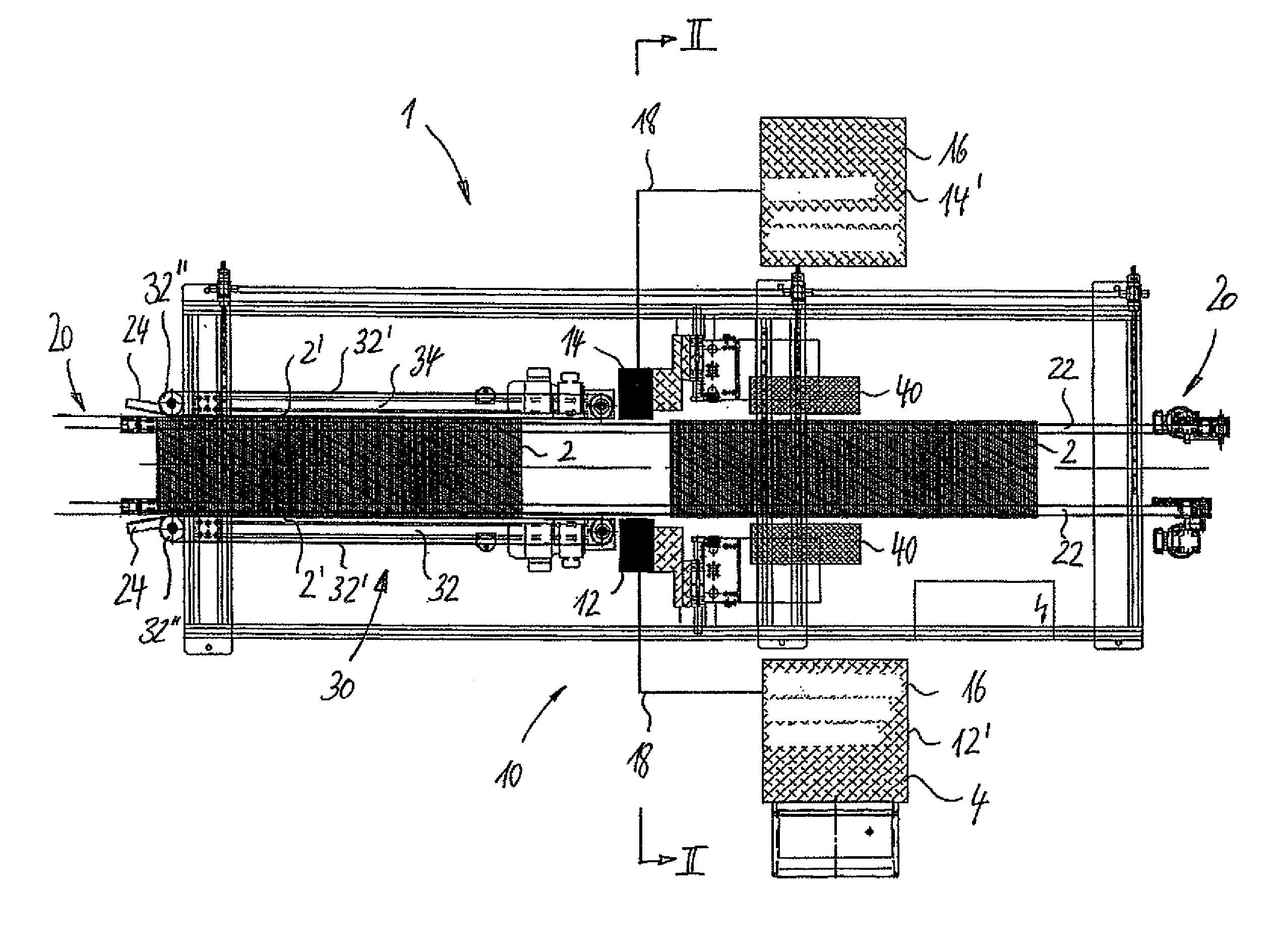
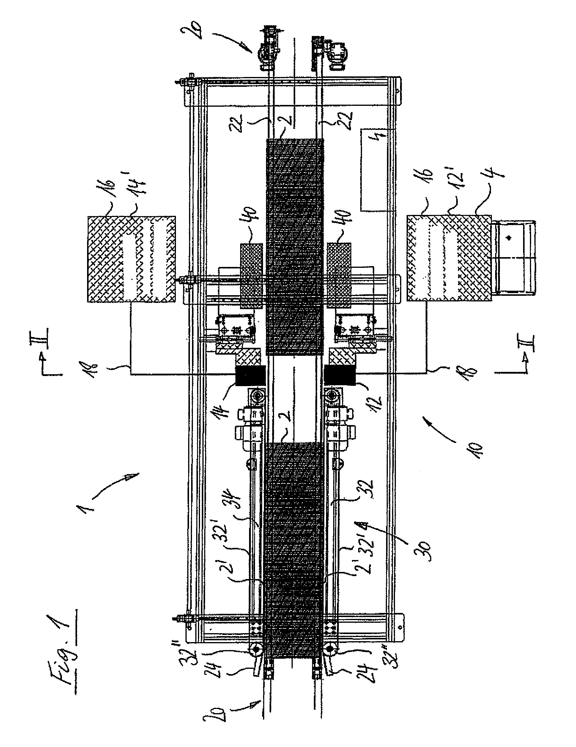
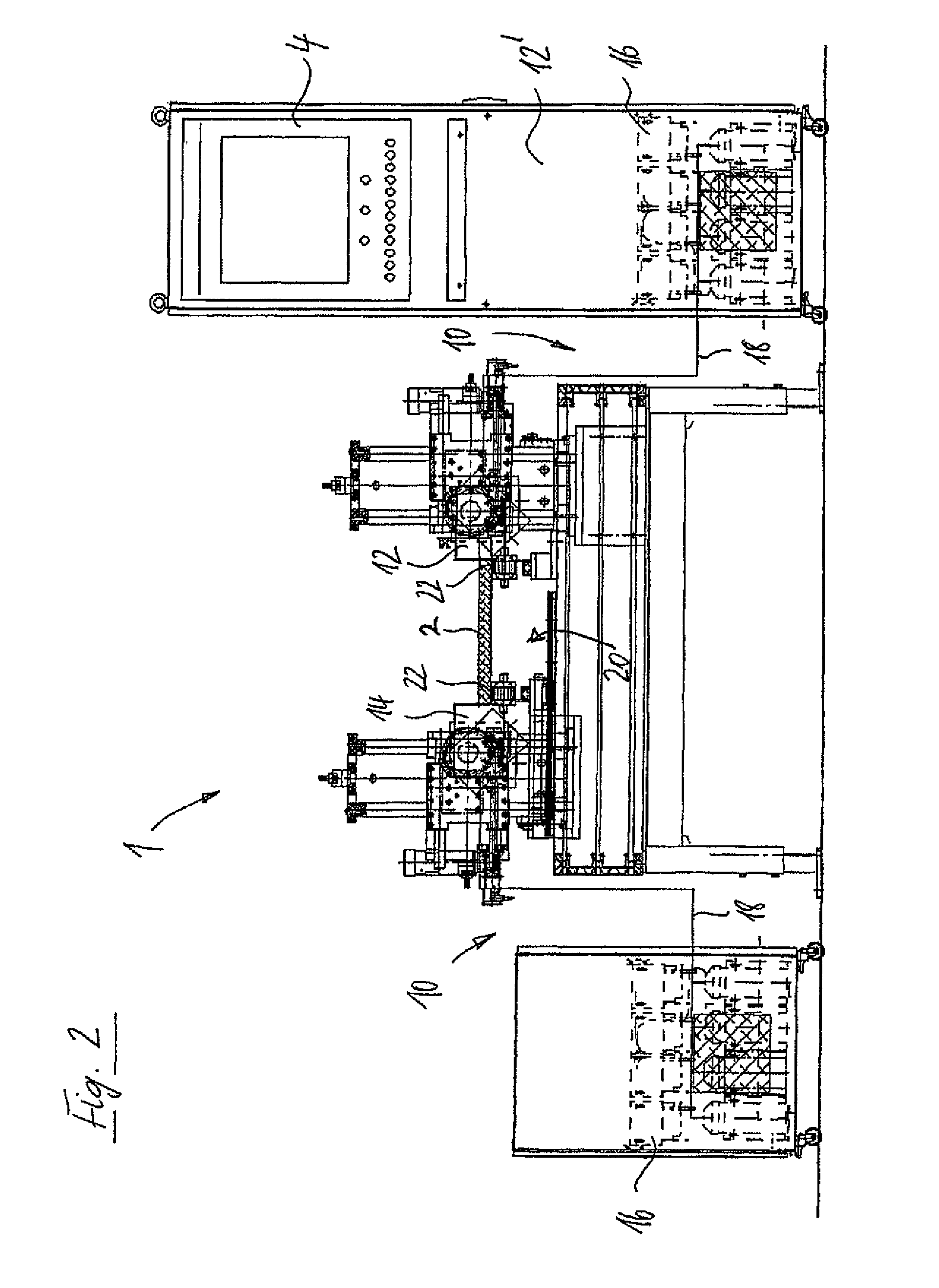
[0021]FIG. 1 is a schematic plan view and FIG. 2 a schematic sectional view of a device 1 for imprinting containers 2. The container 2 is in the present embodiment a cardboard comprising a filling opening which is located on top and was folded beforehand out of a cardboard blank. It should however be noted that the present invention is also applicable to completely different types of containers and also to completely different types of three-dimensional articles such as, for example, plate or strip-like workpieces such as are used in the field of the furniture industry and can often be made of wood, wood materials, plastics materials, etc. or combinations thereof.

[0022]The device 1 has in the present embodiment a printing means 10 comprising two printing units 12, 14 which are configured in the present embodiment as ink-jet print heads comprising a...


PUM


Abstract

The invention relates to a method for imprinting a three-dimensional article, in particular a container and / or workpiece, and comprises utilizing a printing means, in particular an ink-jet printing means, for imprinting a surface of the three-dimensional article, and a conveyor means for bringing about a relative movement between the printing means and the three-dimensional article to be imprinted. The method according to the invention is characterised in that it further utilizes a positioning means which is configured to bring the surface to be imprinted of the three-dimensional article into a predetermined relative relationship to, in particular a predetermined distance from, the printing means.

Description

CROSS-REFERENCE TO RELATED APPLICATIONS[0001]The present application claims the benefit of EP Application No. 07 006247.6, filed Mar. 27, 2007, which is hereby incorporated by reference in its entirety.TECHNICAL FIELD[0002]The invention relates to a device for imprinting a three-dimensional article, in particular a container and / or workpiece, according to the preamble of claim 1.PRIOR ART[0003]Three-dimensional articles, such as for example plate-like workpieces from the field of the furniture industry, are increasingly being imprinted with various patterns which are desired by the customers, for example by means of an ink-jet printing device. Thus, for example, EP 1 726 443 A discloses a generic device for imprinting workpieces in the region of a narrow face, with which high-quality patterns can be produced. However, it has been found that the desired quality of the printed image cannot be achieved in some cases, for example in deformable or non-uniform workpieces.PRESENTATION OF T...

Claims


Application Information

Patent Timeline
Patent Type & Authority Patents(United States)
IPC IPC(8): B41J2/01
CPCB41J3/4073B41J3/543B41J2/01
Inventor ALBRECHT, LUDWIGFREY, KARL
Owner HOMAG HOLZBEARBEITUNGSSYST
Why Eureka
Try Eureka