Tempered glass and method for producing same

a technology of tempered glass and glass, applied in the field of tempered glass, to achieve the effect of high surface quality, high end surface quality, and efficient supply

Inactive Publication Date: 2014-06-19
NIPPON ELECTRIC GLASS CO LTD
View PDF2 Cites 73 Cited by
  • Summary
  • Abstract
  • Description
  • Claims
  • Application Information

AI Technical Summary

Benefits of technology

[0035]The tempered glass of the present invention has the property of being etched properly, and hence etching for a short time can remove the parts excluding masked parts. As a result, each shape necessary to be used in a cellular phone, a tablet PC, and the like can be efficiently provided to each of the masked parts, and the masked parts can each have high surface quality and high end surface quality. In addition, the tempered glass of the present invention has high ion exchange performance, thus having a high mechanical strength and having a variation in mechanical strength to a small extent. Further, the tempered glass of the present invention has a low density, enabling production of a lighter tablet PC, and has a high strain point, thus being able to undergo a high-quality patterning.

Problems solved by technology

Thus, such devices as the tablet PCs each involve the issues of how to reduce the mass of the device and how to reduce the total thickness thereof.

Method used


Image

  • Tempered glass and method for producing same
  • Tempered glass and method for producing same

Examples


example 1

[0101]Hereinafter, examples of the present invention are described. Note that the following examples are merely illustrative. The present invention is by no means limited to the following examples.

[0102]Tables 1 to 3 show Examples of the present invention (Samples Nos. 1 to 21). Note that, in the tables, the term “Not measured” means that measurement has not yet been performed.

TABLE 1ExamplesNo. 1No. 2No. 3No. 4No. 5No. 6No. 7GlassSiO261.160.361.661.461.157.458.7compositionAl2O312.913.09.811.012.313.313.1(mol %)MgO6.56.66.66.66.56.76.7CaO———————B2O3———————ZrO2—————1.11.1Li2O———————Na2O15.916.016.116.016.016.416.2K2O3.53.53.53.53.53.63.6P2O5—0.52.31.40.51.40.5SnO2—0.10.10.10.10.10.1SO30.03——————Cl0.07——————Mg + Ca6.56.66.66.66.56.76.6(Al + Na + P) / Si0.50.50.50.50.50.50.5(B + Na) / Si0.260.270.260.260.260.290.28P / Si00.0080.0380.0230.0080.0250.008Al / Si0.20.20.20.20.20.20.2Na / Al1.21.21.61.51.31.21.2ρ (g / cm3)2.472.482.462.472.472.512.51α (×10−7 / ° C.)102102110105103104101Ps (° C.)5855845535...

example 2

[0116]Glass raw materials blended so as to achieve the glass composition described in Sample No. 21 were fed into a continuous melting furnace and were melted under heating, followed by fining. After that, the resultant molten glass was formed into a glass sheet having a thickness of 0.8 mm by a float method. Subsequently, the glass sheet obtained was processed into a glass sheet having a size of 1 m by 1.2 m, and then ion exchange treatment was performed by immersing the sheet in a KNO3 molten salt at 420° C. for 2 hours.

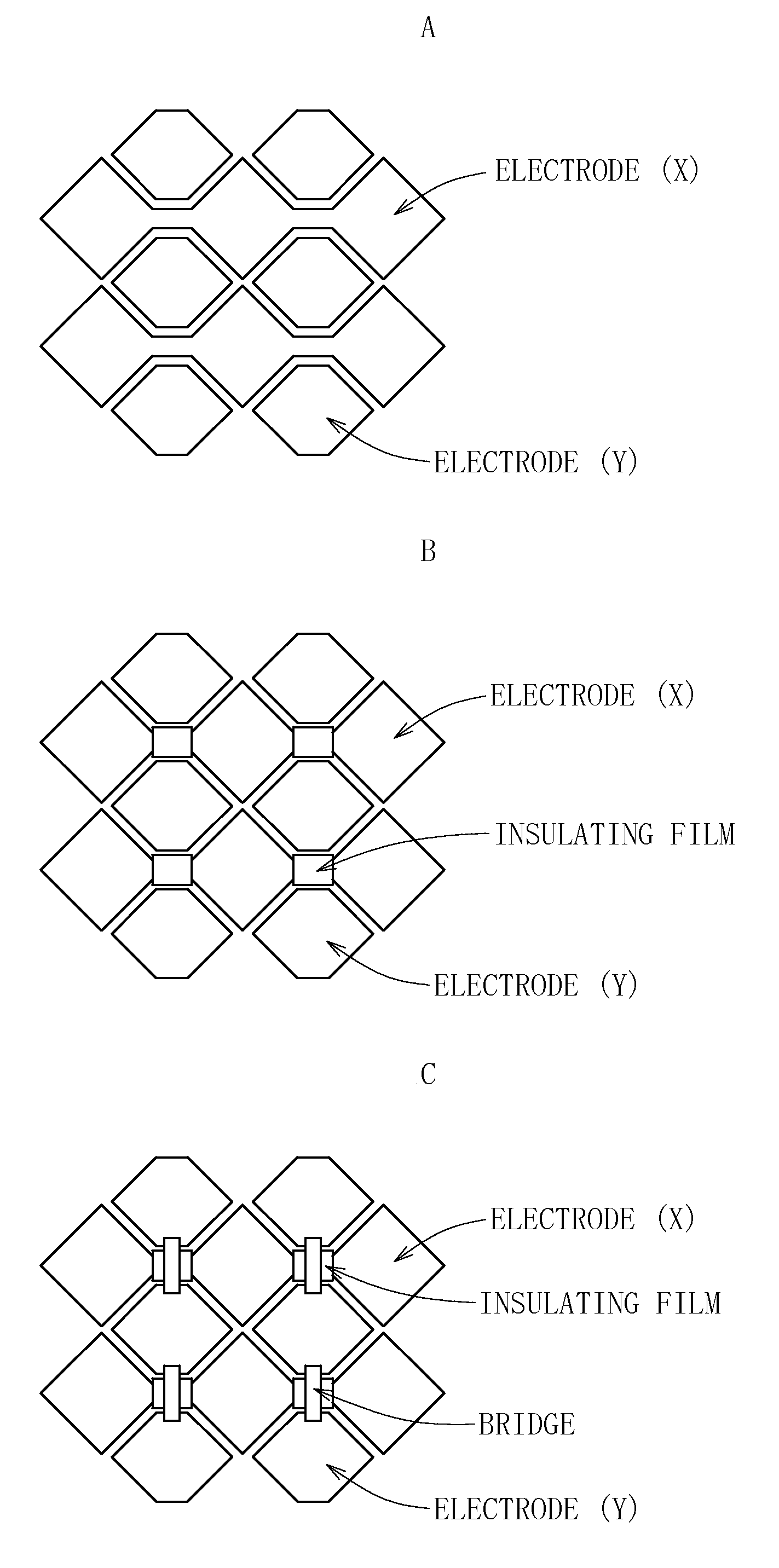
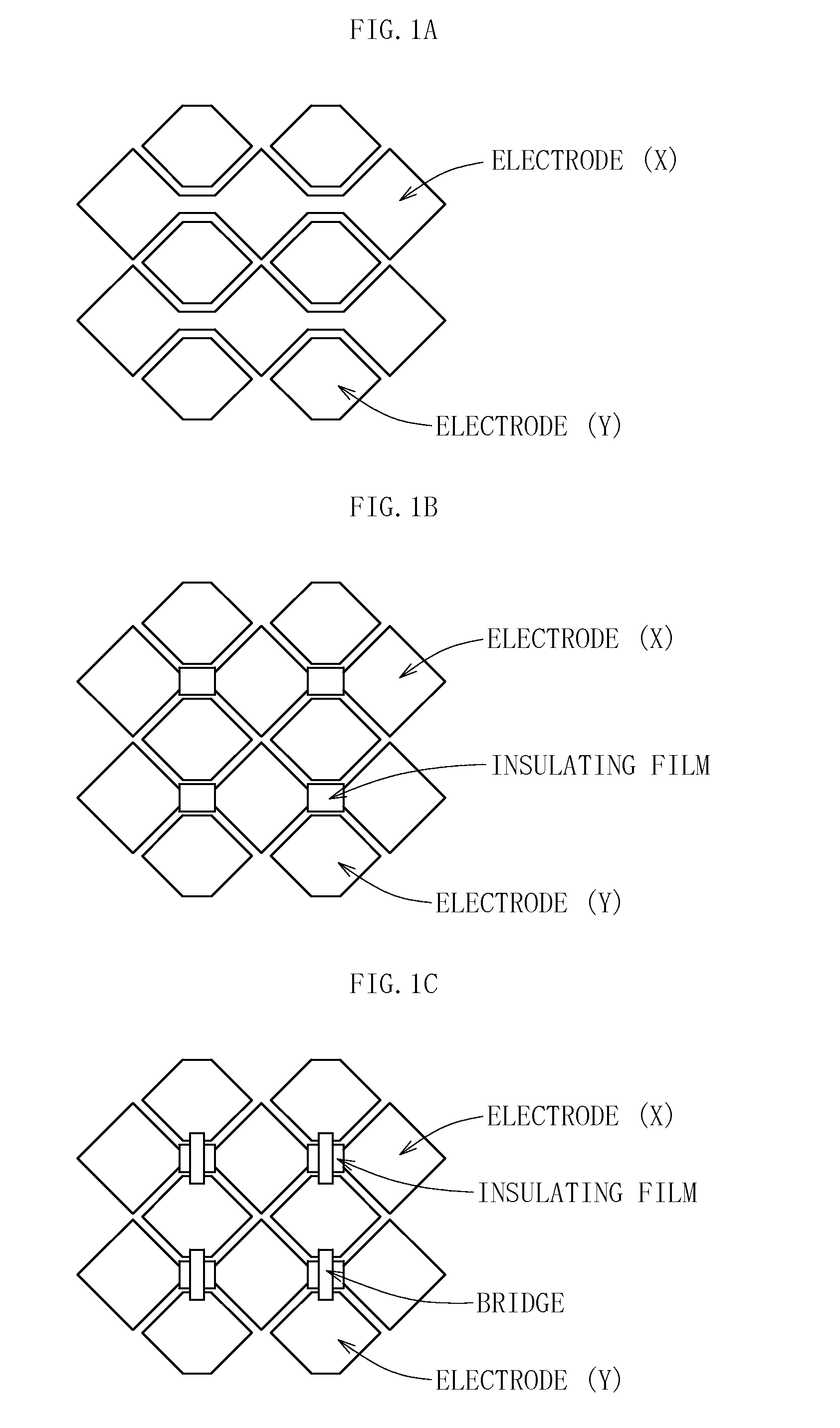
[0117]After a rectangular ITO patterning (for the XY directions) was performed as illustrated in FIG. 1A with respect to the resultant tempered glass, a patterning for forming an insulating film was performed as illustrated in FIG. 1B and a metal-film-bridge patterning (in the Y direction) was then performed as illustrated in FIG. 1C. Thus, a touch panel sensor was formed on the tempered glass.

[0118]Subsequently, masking with Au was performed so that each resultant...


PUM

PropertyMeasurementUnit
molar ratioaaaaaaaaaa

Abstract

A tempered glass of the present invention is a tempered glass having a compression stress layer in a surface thereof, the tempered glass comprising, as a glass composition in terms of mol %, 45 to 75% of SiO2, 3 to 15% of Al2O3, 0 to 12% of Li2O, 0.3 to 20% of Na2O, 0 to 10% of K2O, and 1 to 15% of MgO+CaO, and having a molar ratio (Al2O3+Na2O+P2O5)/SiO2 of 0.1 to 1, a molar ratio (B2O3+Na2O)/SiO2 of 0.1 to 1, a molar ratio P2O5/SiO2 of 0 to 1, a molar ratio Al2O3/SiO2 of 0.01 to 1, and a molar ratio Na2O/Al2O3 of 0.1 to 5, characterized in that the surface or an end surface of the tempered glass is etched after tempering treatment.

Description

TECHNICAL FIELD[0001]The present invention relates to a tempered glass and a production method for the same, and more particularly, to a tempered glass suitable for a cover glass for a cellular phone, a digital camera, a personal digital assistant (PDA), or a solar cell, or a glass substrate for a display, in particular, a touch panel display, and a production method for the same.BACKGROUND ART[0002]Devices such as a cellular phone, a digital camera, a PDA, a touch panel display, a large-screen television, and a wireless charging system tend to be more widely used.[0003]A tempered glass produced by performing tempering treatment such as ion exchange treatment is used in each of those devices (see Patent Literature 1 and Non Patent Literature 1).[0004]In conventional devices, there has been adopted a structure in which a touch panel sensor is formed on a display module and a tempered glass (protective member) is placed over the touch panel sensor.[0005]Further, although small devices...

Claims


Application Information

Patent Timeline
Patent Type & Authority Applications(United States)
IPC IPC(8): C03C3/11C03C3/097C03C21/00C03B33/02C03C15/00
CPCC03C3/087C03C3/097C03C15/00C03C21/002Y10T428/315Y10T428/24355C03C3/11C03C3/085C03B33/02C03C3/091C03C21/00G02F1/13
Inventor MURATA, TAKASHITOJYO, TAKAKO
Owner NIPPON ELECTRIC GLASS CO LTD
Why Eureka
Try Eureka