Centrifugal blower

a centrifugal blower and centrifugal technology, which is applied in the direction of machines/engines, stators, liquid fuel engines, etc., can solve the problems of deviating the tongue gap ratio thus varied, and insufficient suppression of periodic noise generation, so as to suppress the generation of periodic noise due to interference between the tongue and the impeller, and suppress the generation of nois

Active Publication Date: 2012-01-31
MITSUBISHI HEAVY IND LTD
View PDF12 Cites 8 Cited by
  • Summary
  • Abstract
  • Description
  • Claims
  • Application Information

AI Technical Summary

Benefits of technology

[0013]With this measure, the hanging portion is disposed in a stagnant flow region (which corresponds to a dead region) that would otherwise be formed because a flow in the spiral flow passage would collide with the extension. Therefore, after colliding with the extension, the air flows parallel with the hanging portion without stagnation. As a result, the level of noise due to a stagnant flow can be made lower than in a case that the hanging portion is not formed. That is, filling in the stagnant flow region with the hanging portion suppresses generation of an unstable flow in the region concerned and suppresses a reverse flow from the spiral flow passage to the impeller. The generation of noise due to a reverse flow can thus be suppressed.
[0032]According to the centrifugal blower of the invention, since the high-pressure region formed varies depending on the position in the axial line direction, a blade passes the high-pressure region with variable timing that depends on the position in the axial line direction. This provides the advantage that the generation of periodic noise due to interference between the tongue and the impeller can be suppressed. The feature that the gap between the extension and the impeller is kept approximately constant in the circumferential direction of the impeller provides the advantage that the generation of noise can be suppressed.

Problems solved by technology

However, in the technique of the above Patent Citation 1, there is a possibility that the tongue gap ratio thus varied is deviated from an optimum value to generate the noise other than periodic noise.
And there is another problem that the generation of periodic noise is not suppressed sufficiently.

Method used


Image

  • Centrifugal blower
  • Centrifugal blower
  • Centrifugal blower

Examples


embodiment 1

[0061]A centrifugal blower according to a first embodiment of the present invention will be hereinafter described with reference to FIGS. 1-7.

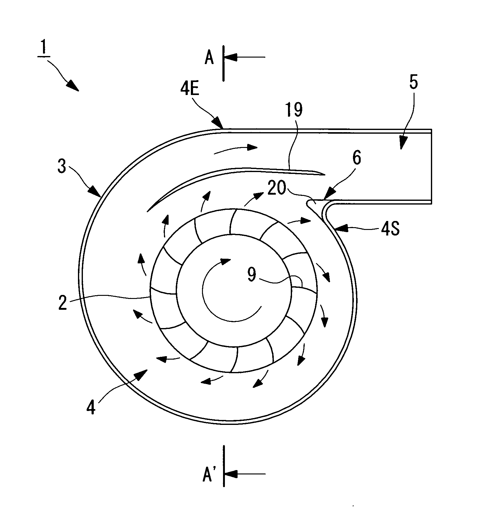
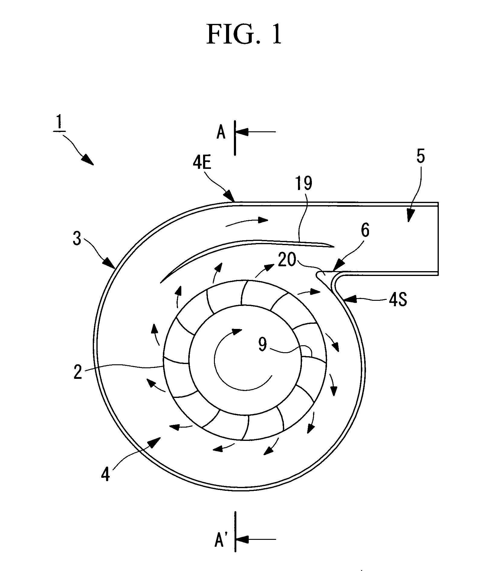
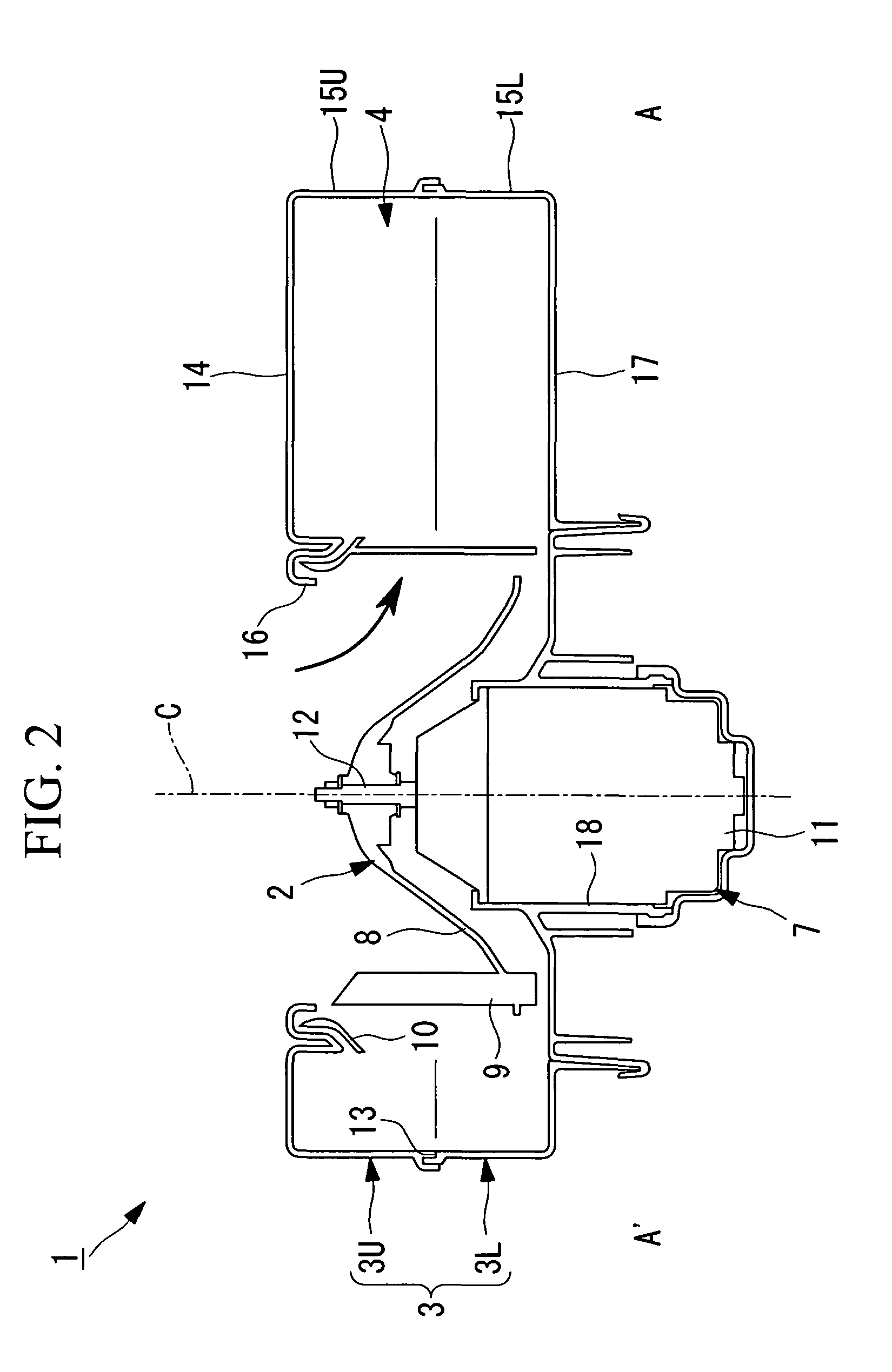
[0062]FIG. 1 is a schematic view showing the configuration of a centrifugal blower according to this embodiment. FIG. 2 is a sectional view showing the configuration of the centrifugal blower of FIG. 1.

[0063]The centrifugal blower 1 according to the embodiment is used as a blower of a vehicular air conditioner. As shown in FIGS. 1 and 2, the centrifugal blower 1 is equipped with an impeller 2, a casing 3 which houses the impeller 2, a spiral flow passage 4 which is formed around the impeller 2 in the casing 3, a diffuser flow passage 5 which extends in a tangential direction from the winding end of the spiral flow passage 4, a tongue 6 which guides air from the spiral flow passage 4 to the diffuser flow passage 5 and suppress air inflow from the winding end to the winding origin of the spiral flow passage 4, and a drive unit 7 which rotation-d...

embodiment 2

[0128]Next, a second embodiment of the invention will be described with reference to FIGS. 8-10.

[0129]A centrifugal blower according to this embodiment is the same in basic configuration as the centrifugal blower according to the first embodiment, and is different from the latter in the structure of the upper tongue. Therefore, in this embodiment, the structure of the upper tongue and components neighboring it will be described with reference to FIGS. 8-10 and the other components etc. will not be described.

[0130]FIG. 8 is an enlarged partial view showing the structure of the upper tongue of the centrifugal blower according to this embodiment and is a see through view of the upper tongue as viewed from the top plate 14.

[0131]Components having the same components in the first embodiment will be given the reference symbols as the latter and will not be described.

[0132]As shown in FIG. 8, an upper tongue (one tongue) 106U of the centrifugal blower 101 is a curved wall that connects a p...

modification 1

of Embodiment 2

[0149]Next, a first modification of the second embodiment of the invention will be described with reference to FIGS. 11-13.

[0150]A centrifugal blower according to this modification is the same in basic configuration as the centrifugal blower according to the second embodiment, and is different from the latter in the structure of the upper tongue. Therefore, in this modification, the structure of the upper tongue and components neighboring it will be described with reference to FIGS. 11-13 and the other components etc. will not be described.

[0151]FIG. 11 is an enlarged partial view showing the structure of the upper tongue of the centrifugal blower according to this modification and is a see through view of the upper tongue as viewed from the top plate 14.

[0152]Components having the same components in the second embodiment will be given the reference symbols as the latter and will not be described.

[0153]As shown in FIG. 11, an upper tongue (one tongue) 206U of the cent...


PUM


Abstract

It is intended to provide a centrifugal blower capable of suppressing the generation of noise including periodic noise that is caused by interference between a tongue and an impeller. The centrifugal blower is provided with an impeller (2) provided with plural blades around a rotating shaft; a casing (3) which houses the impeller (2) and has a suction portion at one end in an axial line direction of the rotating shaft; a spiral flow passage (4) formed around the impeller (2) in the casing (3); and a tongue (6) for suppressing inflow of air from a winding end to a winding origin of the spiral flow passage (4). The centrifugal blower is characterized in that an extension (20) is provided at a tip of the tongue (6) in a reverse rotational direction that is reverse to a rotational direction of the impeller (2) in such a manner that it projects in the reverse rotational direction by a length that varies depending on the position in the axial line direction and that the gap between itself and the impeller (2) in the radial direction of the impeller (2) is kept approximately constant.

Description

TECHNICAL FIELD[0001]The present invention relates to a centrifugal blower which is suitable for suppressing the generation of periodic noise.BACKGROUND ART[0002]In centrifugal blowers, it is known that periodic noise is generated by interference between an impeller and a tongue. This periodic noise has blade-passing-frequency whose frequency is proportional to the rotational speed (N) and the number of blades (Z) of the impeller.[0003]In one known method for suppressing such periodic noise, a large gap is formed between the outer diameter of the impeller and the tongue. However, this method deteriorates the aerodynamic performance of the centrifugal blower. Therefore, to maintain the aerodynamic performance, that is, the airflow rate, it is necessary to increase the rotational speed of the impeller. However, this results in a problem that the overall noise level (which corresponds to an integration value of noise at respective audible frequencies) of the centrifugal blower is deter...

Claims


Application Information

Patent Timeline
Patent Type & Authority Patents(United States)
IPC IPC(8): F04D29/44
CPCF04D29/422F04D29/4226F04D29/663F05D2250/232
Inventor EGUCHI, TSUYOSHISUZUKI, ATSUSHINAKAO, MITSUHIROTOMINAGA, TETSUO
Owner MITSUBISHI HEAVY IND LTD
Why Eureka
Try Eureka