Drive and evaluation unit

a technology of evaluation unit and drive, which is applied in the direction of motor/generator/converter stopper, dynamo-electric converter control, shape/form/construction of magnetic circuit, etc., to achieve the effect of reducing the likelihood of system-characteristic vibration modulated to the armature current miscounting amplitudes

Active Publication Date: 2012-01-31
ROBERT BOSCH GMBH
View PDF6 Cites 6 Cited by
  • Summary
  • Abstract
  • Description
  • Claims
  • Application Information

AI Technical Summary

Benefits of technology

[0006]The object of the invention is an improved drive and evaluation unit, with which the likelihood of miscounts of the amplitudes of a system-characteristic vibration modulated to the armature current is reduced.

Problems solved by technology

In known drive and evaluation units, it is problematic that the amplitudes of the vibration modulated to the armature current usually have such a low intensity that miscounts and hence incorrect position determinations result.

Method used


Image

  • Drive and evaluation unit
  • Drive and evaluation unit
  • Drive and evaluation unit

Examples


Embodiment Construction

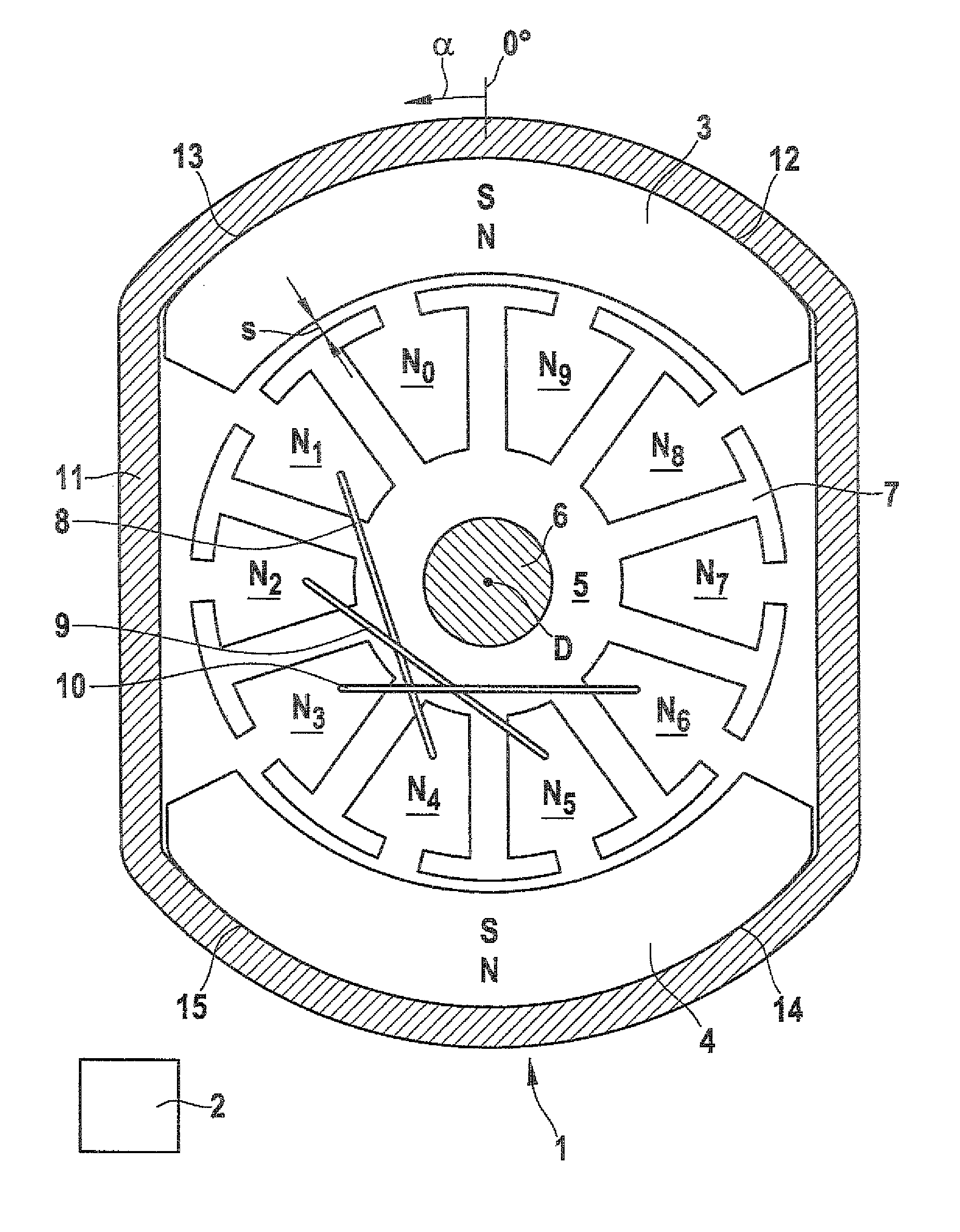
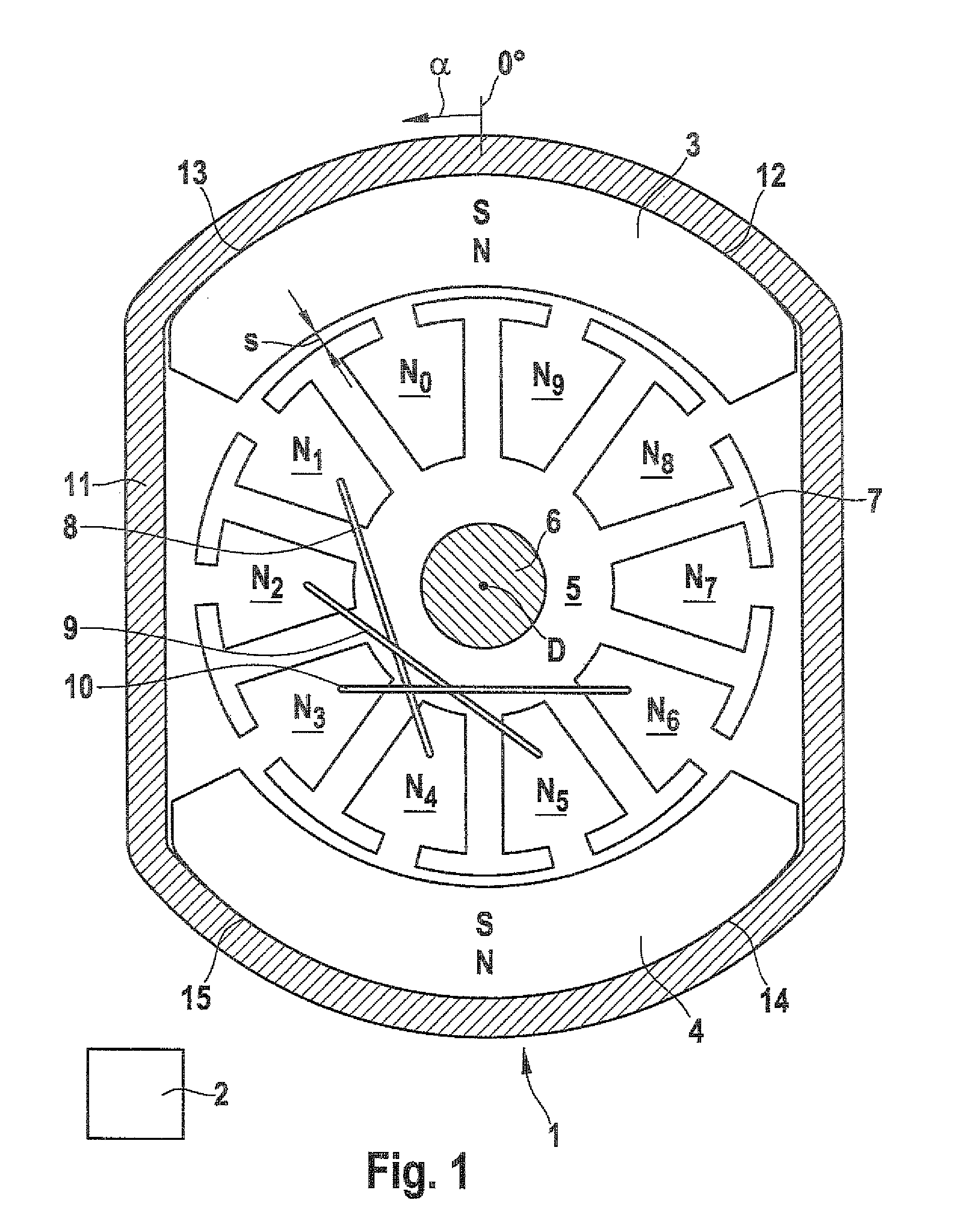
[0017]In FIG. 1, a commutator motor 1 and an evaluation unit 2 are shown. The evaluation unit 2 is connected, via the following elements of electrical connecting lines not shown, to the current supply circuit of the two commutator brushes, not shown. The evaluation unit 2 counts the amplitudes of a vibration that is proportional to the rpm of the commutator motor 1 and is modulated to the armature current. This vibration has its source in the alternating commutation of the armature windings and in the course of the induced voltage inside a partial coil.

[0018]The commutator motor 1 has two diametrically opposed permanent magnets 3, 4 of opposite polarity. A substantially cylindrical armature 5 with an armature shaft 6 is disposed rotatably radially inside the permanent magnets 3, 4. The rotary axis of the armature shaft 6 is marked D. The armature 5 has ten V-shaped slots N0 through N9 spaced apart in the circumferential direction. Two adjacent slots are each demarcated from one anot...


PUM


Abstract

The invention relates to a drive and evaluation unit for displacing an object to be displaced, particularly for raising and lowering a side window in a motor vehicle. The drive includes a commutator motor with a stator having two diametrically opposed permanent magnets. The magnets have cross-sectional shapes of a respective peripheral contour segment, having a radial inner peripheral contour segment which encompasses an armature over a respective inner peripheral angle. The armature is provided with ten grooves spaced around its periphery for holding armature windings that are configured as lap windings. The evaluation unit includes a device for determining the rotational position of the armature by evaluating the ripple count of the armature current. According to the invention, the armature windings are configured as short pitch windings, and the inner peripheral angle of the radial inner peripheral contour segment of at least one of the magnets is between 101° and 111°.

Description

CROSS-REFERENCE TO RELATED APPLICATION[0001]This application is a 35 USC 371 application of PCT / EP 2007 / 052616 filed on Mar. 20, 2007.BACKGROUND OF THE INVENTION[0002]1. Field of the Invention[0003]The invention relates to a drive and evaluation unit, in particular for raising and lowering a side window in a motor vehicle.[0004]2. Description of the Prior Art[0005]For positional determination of displacement systems driven by commutator motors, it is known to evaluate the waviness of the armature current. This method is called the ripple count method. In it, a frequency that is proportional to the motor rpm and is modulated to the armature current is analyzed by means of an evaluation unit. The possible system-characteristic frequency that can be used for this purpose is caused by the commutation between the individual armature windings and thus makes it possible to subdivide one revolution of the electric motor into a number of partial revolutions corresponding to the number of com...

Claims


Application Information

Patent Timeline
Patent Type & Authority Patents(United States)
IPC IPC(8): H02K1/17H02K3/12
CPCH02K23/04H02K23/30H02K23/66H02K13/04G01R31/34
Inventor HAUSSECKER, WALTERBUEHLER, DIRKFROEHLICH, PETERSCHRAMM, FRANCOISHERTWECK, VOLKER
Owner ROBERT BOSCH GMBH
Why Eureka
Try Eureka