
Method for production of mixed vapour

a technology of mixed vapour and production method, which is applied in the direction of steam engine plants, machines/engines, mechanical equipment, etc., can solve the problems of high working pressure, high materials used, and disadvantageous mixed vapor temperatures and working pressure in vapor generators and lines, so as to reduce the amount of energy used, the operating temperature, and the operating pressure

Inactive Publication Date: 2012-02-07
LESA MASCH GMBH
View PDF9 Cites 2 Cited by
  • Summary
  • Abstract
  • Description
  • Claims
  • Application Information

AI Technical Summary

Benefits of technology

"The present invention provides a method for producing mixed vapor that improves efficiency and reduces energy usage, operating temperature, and pressure. This is achieved by producing a mixed vapor in a low-temperature pressure chamber from a non-polar fluid and a polar fluid, adding it to a second pressure chamber, compressing it with a heat engine, and expanding it to create wet vapor, which is then returned to the first pressure chamber. This method allows for the use of renewable energies for operating heat engines economically and cost-effectively while simultaneously increasing efficiency. The work released by the heat engine can be transmitted to a crank mechanism that produces a rotational movement, which can be transmitted to an alternator for producing electrical energy. This invention provides a cost-effective, energy-efficient, and resource-saving method for producing mixed vapor."

Problems solved by technology

With these, the high mixed vapor temperatures and working pressures in the vapor generators and lines are disadvantageous.
This results in particularly high demands on the materials used.
All of this is time-consuming and associated with high costs.
Furthermore, producing a mixed vapor with which it is possible to operate a heat engine with adequate output requires a significant amount of energy.

Method used


Image

  • Method for production of mixed vapour
  • Method for production of mixed vapour

Examples


Embodiment Construction

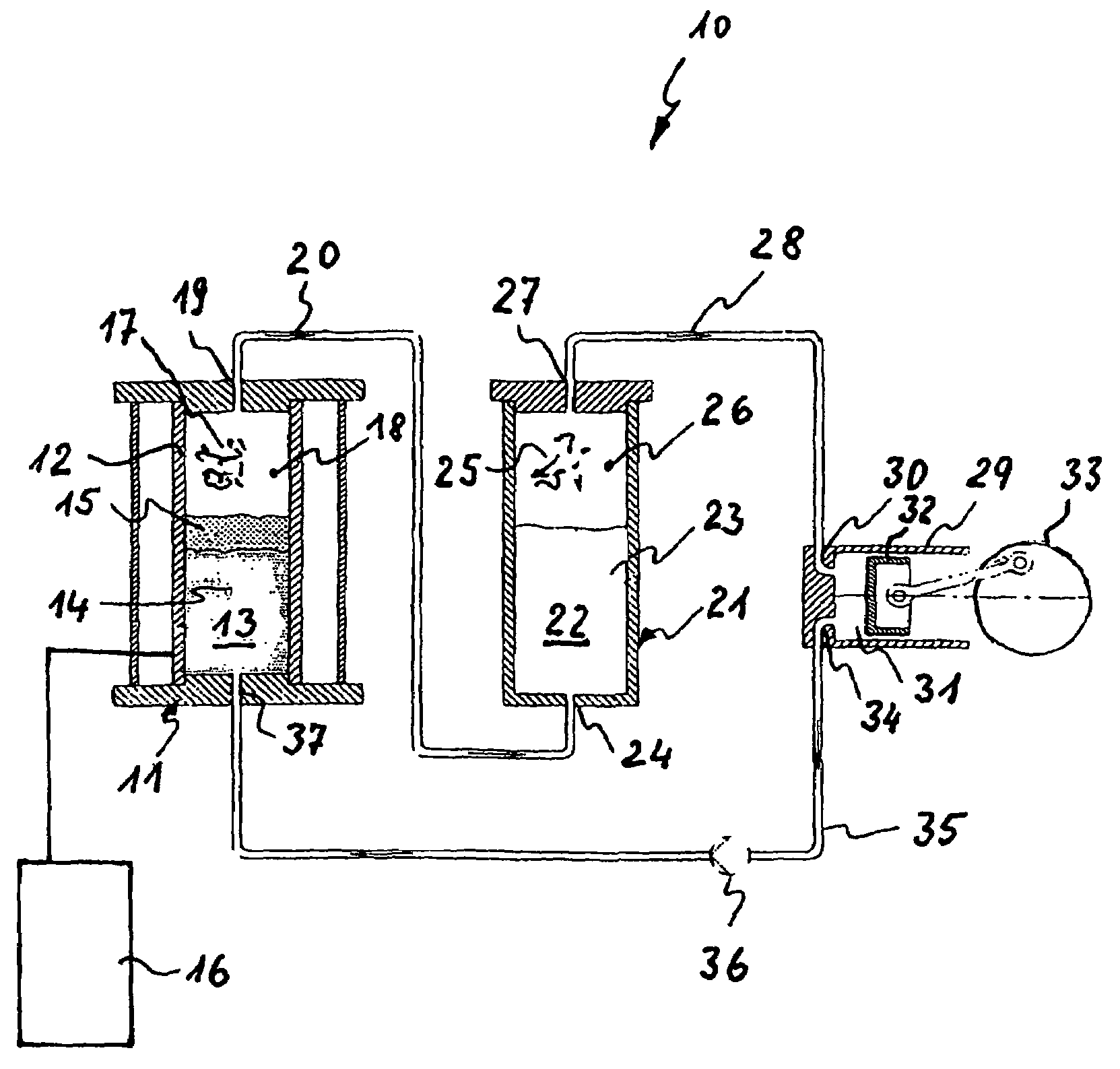
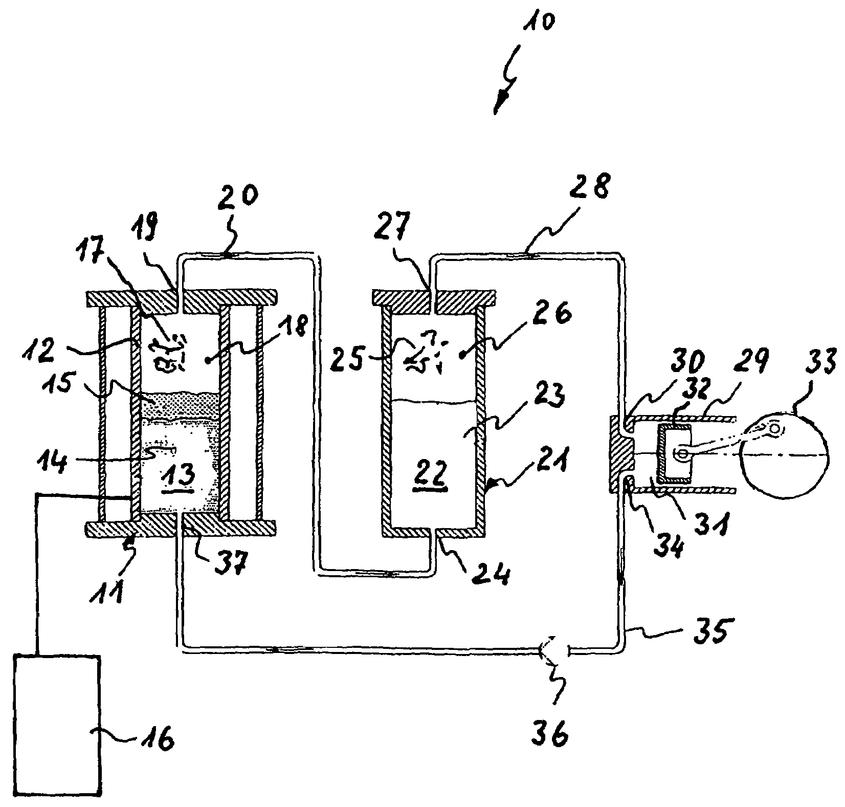
[0022]The apparatus 10 depicted in the sole FIGURE essentially comprises at least one mixed vapor generator 11 that is provided with a low pressure vessel 12. The low pressure vessel 12 has a first pressure chamber 13 in which a first polar fluid 14, for instance water, and at least one non-polar fluid 15, for instance benzene, are present in liquid form. There is preferably a greater quantity of the polar fluid 14 than the non-polar fluid 15.

[0023]A heat exchanger 16, for instance any desired boiler system (schematically depicted), is associated with the mixed vapor generator 11. This heat exchanger 16 can act on and evaporate the fluids 14 and 15.

[0024]The heat exchanger 16 is operated with solar energy or geothermal energy. It is also possible to use renewable energy sources such as wood, for instance in the form of wood chips from first product leftovers. Any other type of biomass is also conceivable, provided it is present in an appropriate quality and quantity for being conver...


PUM


Abstract

Method for production of mixed vapors at low temperatures. The thermal energy stored in the mixed vapors is intended to be converted to mechanical energy in a thermal power machine, in order to operate an electrical generator.

Description

BACKGROUND OF THE INVENTION[0001]The invention relates to a method for production of mixed vapor.[0002]The physical processes described in the following relate to heat engines that are operated with mixed vapor in a cyclical process. Applicable physical phenomena and laws are sufficiently known from thermodynamics. Their fundamentals shall not be explained in greater detail here.[0003]Heat engines are normally operated with vapor. To produce vapor, liquids are subjected to high pressure in a vapor generator and evaporated by adding energy. This vapor can then be converted to mechanical energy.[0004]It has been demonstrated that the efficiency of heat engines can be improved provided they are operated with mixed vapors. AT 155744 describes the production of mixed vapor from two or more polar and non-polar liquids that re-separate in the liquid phase.[0005]The mixed vapor is brought to a complete or partial liquid state using one or more successive expansions and compressions during w...

Claims


Application Information

Patent Timeline
Patent Type & Authority Patents(United States)
IPC IPC(8): F01K25/08F01K5/00F01K3/00F01K25/06F01K7/00F01K25/00
CPCF01K25/06F01K21/04F01K25/10F01K27/00
Inventor SCHAEFFER, BERNHARD
Owner LESA MASCH GMBH
Learn More