Damper

a technology of damper and damper body, which is applied in the direction of shock absorbers, mechanical devices, transportation and packaging, etc., can solve the problems damage to the hydraulic damper, and affect the ride comfort. , to achieve the effect of deterioration of ride comfort in the vehicl

Active Publication Date: 2012-02-07
TOYOTA JIDOSHA KK +1
View PDF23 Cites 43 Cited by
  • Summary
  • Abstract
  • Description
  • Claims
  • Application Information

AI Technical Summary

Benefits of technology

[0014]The present invention has been accomplished in view of the above-mentioned problems and it is an object of the present invention to provide a damper capable of improving both reliability and ride comfort in a vehicle while adopting a construction of generating a damping force by utilizing an electromagnetic force of a motor.
[0016]According to the damper of the present invention, the hydraulic damper is connected in series with the actuator and is disposed on the unsprung member side, so if a high-frequency oscillation, e.g. oscillation of a relatively large acceleration, is inputted to the unsprung member when the vehicle is running on a rough road or gets on a projection of a road surface, the hydraulic damper absorbs this oscillation energy and, coupled with a oscillation transfer suppressing effect induced by the biasing means, the hydraulic damper acts to make it hard to transfer the oscillation to the actuator side.
[0017]Thus, the hydraulic damper absorbs the aforesaid oscillation and the biasing means exhibits the oscillation transfer suppressing effect, whereby the transfer of oscillation to the actuator is suppressed. Therefore, the damper of the present invention brings about the effect that the ride comfort in the vehicle is not impaired even in such a case.
[0018]Moreover, as noted above, direct action of a high-frequency oscillation on the actuator is prevented by the hydraulic damper and hence the transfer of a high-frequency oscillation of particularly a large acceleration to the motor is suppressed. As result, the reliability of the actuator as a principal component of the damper is improved and the reliability of the damper is improved while solving the problems of the conventional damper.
[0020]That is, such a problem encountered in the conventional damper as the piston interfering with the cylinder, resulting in deterioration of the ride comfort in the vehicle or of reliability of the damper, is solved.

Problems solved by technology

However, the above conventional damper involves the following problems.
This causes problems.
As a result, an impact resulting from the collision is propagated up to the sprung member of the vehicle body and impairs the ride comfort in the vehicle or in the worst case it may lead to a damage of the hydraulic damper.
Also in this case, as in the above case, the ride comfort in the vehicle is deteriorated and a damage of the hydraulic damper may result.
Thus, there is a problem in point of reliability of the damper.

Method used


Image

  • Damper
  • Damper
  • Damper

Examples


Embodiment Construction

[0026]The present invention will be described below by way of embodiments thereof illustrated in the drawings.

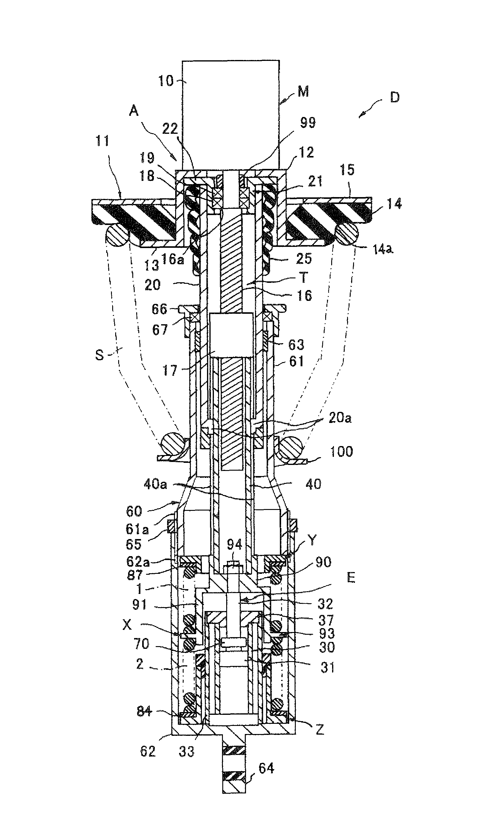
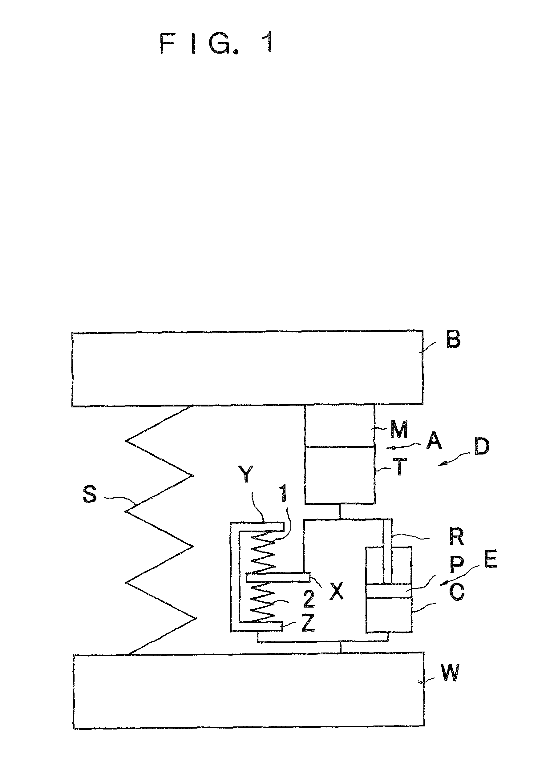
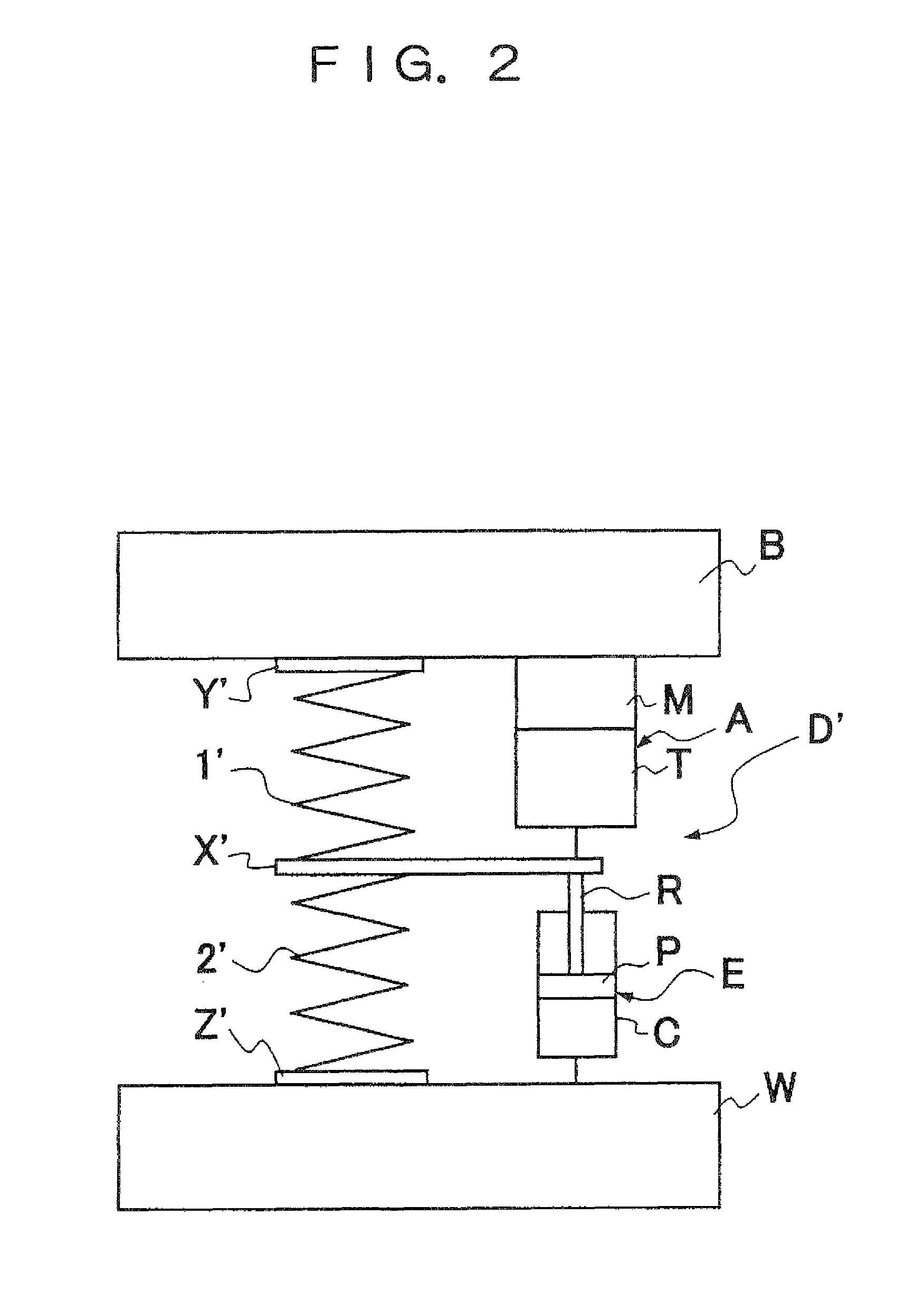
[0027]As shown in FIG. 1, a damper D is interposed between an unsprung member W and a sprung member B and in parallel with a suspension spring S. Basically, the damper D is made up of a hydraulic damper E connected to the unsprung member W, an actuator A connected in series with the hydraulic damper E and also connected to the sprung member B side, springs 1 and 2, as well as a spring seat X and spring seat portions Y, Z, interposed between the actuator A and the unsprung member W and in parallel with the hydraulic damper E and serving as biasing means for biasing the hydraulic damper E in both compressing direction and extending direction.

[0028]The actuator A includes a motion converting mechanism T for transforming a linear motion into a rotational motion and a motor M to which the rotational motion resulting from transformation by the motion converting mechanism T is tran...


PUM


Abstract

A damper is comprised of an actuator (A) connected to a sprung member (B) side of a vehicle, the actuator (A) including a motion converting mechanism (T) for transforming a linear motion into a rotational motion and a motor (M) to which the rotational motion resulting from the transformation by the motion converting mechanism (T) is transmitted; a hydraulic damper (E) including a cylinder (C), a piston (P) inserted slidably into the cylinder (C) and defining two pressure chambers within the cylinder (C), and a rod (R) connected at one end thereof to the piston (P), wherein a linear motion of the actuator (A) being transmitted to one of the rod (R) and the cylinder (C) while the other of the rod (R) and the cylinder (C) being connected to an unsprung member (W) side of the vehicle; and biasing means (1, 2, X, Y, Z) for biasing the hydraulic damper (E) in both compressing and extending directions.

Description

FIELD OF ART[0001]The present invention relates to an improvement of a damper for suppressing a relative movement between a vehicle body and an axle by virtue of an electromagnetic force generated in a motor.BACKGROUND ART[0002]As this type of a damper there has been proposed a damper comprising a hydraulic damper and an actuator for imparting a propelling force to a piston rod of the hydraulic damper, as is disclosed in Japanese Patent Laid-Open Publication No. 2001-180244. According to this proposal, a rod of a hydraulic damper is formed in a tubular shape, a female screw portion is formed on an inner periphery side of the rod, a shaft connected at one end thereof to a rotor of a motor and at an opposite end thereof to a male screw member threadably engaged with the female screw portion of the rod is inserted through the rod of the hydraulic damper, and a piston rod of the hydraulic damper is constituted by the shaft and the rod.[0003]According to the above proposal, force which i...

Claims


Application Information

Patent Timeline
Patent Type & Authority Patents(United States)
IPC IPC(8): F16F15/03
CPCB60G11/15B60G15/062B60G15/063B60G17/021B60G17/0272F16F9/18F16F15/03B60G2202/12B60G2204/1242B60G2204/128B60G2204/41F16F2232/04F16F2232/06
Inventor KONDO, TAKUHIROINOUE, HIROFUMI
Owner TOYOTA JIDOSHA KK
Why Eureka
Try Eureka