Vibration damper with a stop spring

a technology of stop springs and dampers, which is applied in the direction of shock absorbers, mechanical equipment, transportation and packaging, etc., can solve the problems of inability to meet the needs of vibration dampers, the use of short stop springs, and the primarily occurring problem of previous descriptions,

Active Publication Date: 2012-02-07
ZF FRIEDRICHSHAFEN AG
View PDF22 Cites 11 Cited by
  • Summary
  • Abstract
  • Description
  • Claims
  • Application Information

AI Technical Summary

Benefits of technology

[0010]The radial channel is preferably produced by a stamping operation, so that a low-cost manufacturing method can be used, which eliminates the danger that machining burrs could be formed, which could damage the stop spring.
[0012]Especially when the stop spring has at least one discharge groove in one end, it is possible for the discharge groove in the stop spring and the radial channel in the stop surface to overlap at least partially in the installed position of the stop spring, which further improves the flow conditions between working spaces inside and outside of the stop spring.

Problems solved by technology

This possibility is not available in a vibration damper of the single-tube type, the compensating space of which is frequently located downstream from the working space on the side of the piston facing away from the piston rod.
It has also been found that the previously described problem occurs primarily in the case of comparatively long stop springs.
The use of short stop springs, however, does not represent a genuine solution, because it is necessary to maintain a specific damping force characteristic.
The metal angular rings, however generate noise when they strike the piston rod guide, and this interferes with passenger comfort.

Method used


Image

  • Vibration damper with a stop spring
  • Vibration damper with a stop spring
  • Vibration damper with a stop spring

Examples


Embodiment Construction

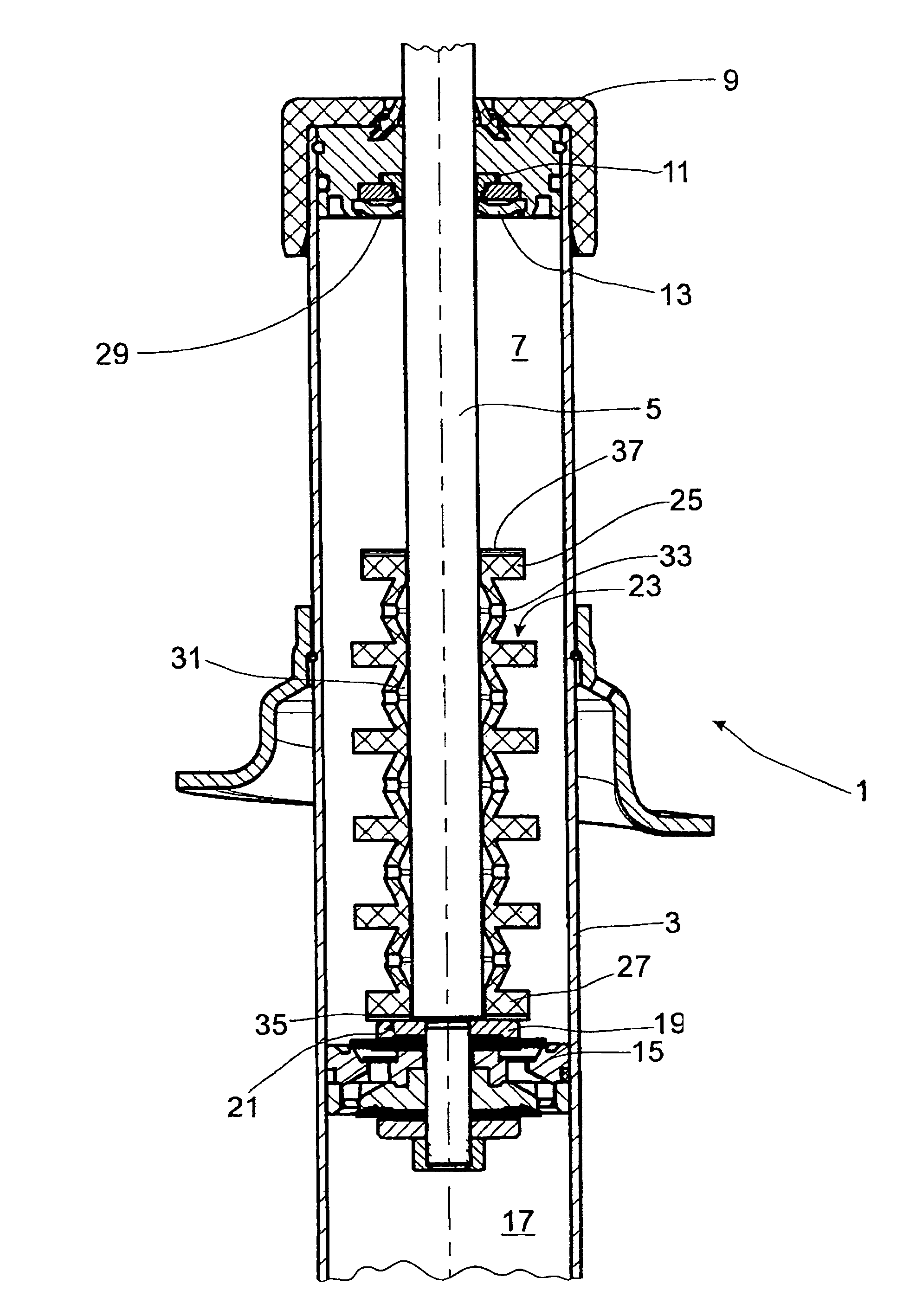
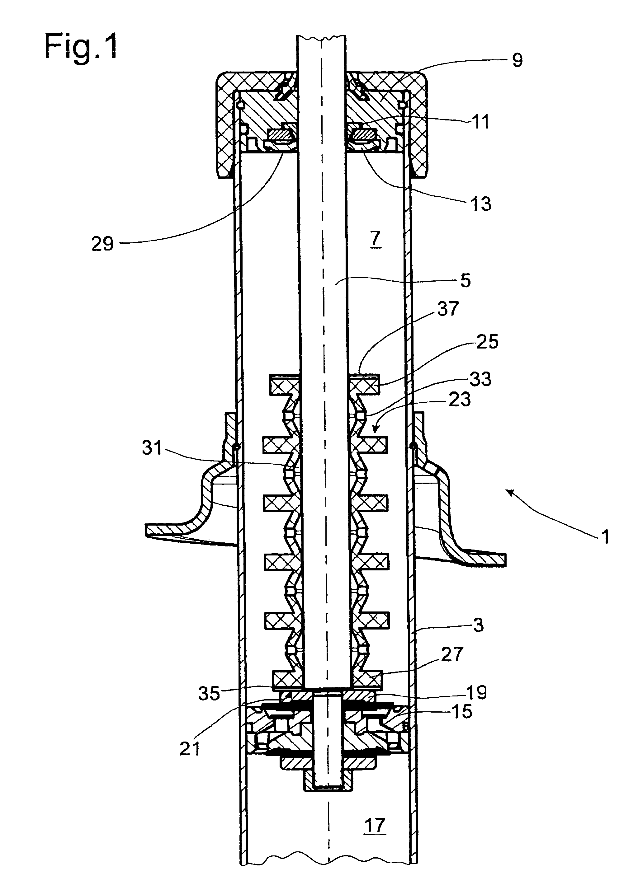
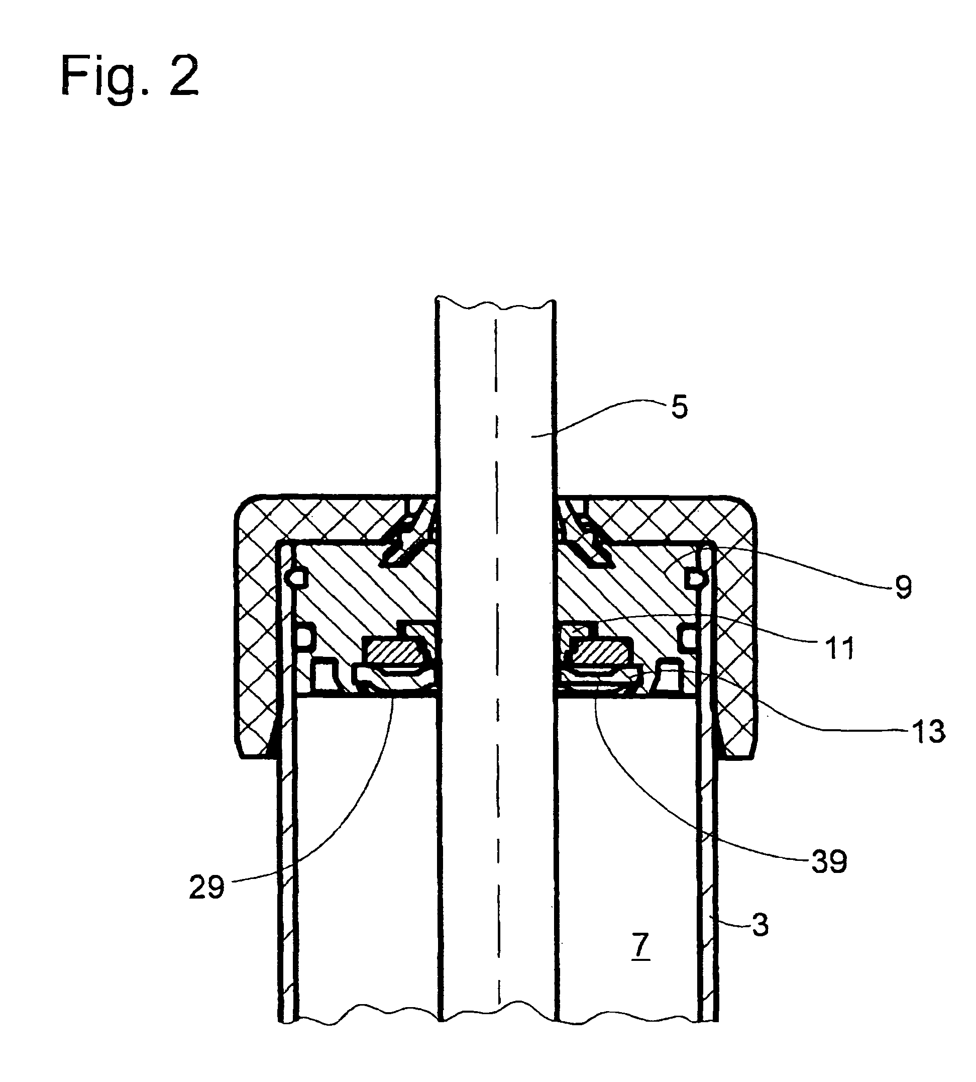
[0021]FIG. 1 shows a vibration damper 1 of the single-tube type with a cylinder 3, in which a piston rod 5 is guided with freedom of axial movement. A working space 7 at one end of the cylinder 3 is closed by a piston rod guide 9 and completely filled with a damping medium, preferably oil. The piston rod guide 9 is equipped with a piston rod seal 11 which is secured axially by a support disk 13.

[0022]A piston 15 separates the working space 7 on the piston rod side from a working space 17 on the side opposite the piston rod and is attached to the piston rod 5. The piston 15 comprises a support disk 19 with a stop surface 21 for an axially floating stop spring 23 which is in the form of a circular ring formed by an elastomeric body. The elastomeric body forming the stop spring 23 has terminal rings 25, 27 at respective ends thereof. Depending on the stroke position of the piston rod, one of the terminal rings 25, 27 comes to rest against the stop surface 21 of the support disk 19 or a...


PUM


Abstract

A vibration damper, comprising a damping medium-filled cylinder, in which a piston rod is guided with freedom of axial movement, where, inside a working space in the cylinder, a stop spring in the form of a circular ring is located, which, after the piston rod has reached a defined stroke position, is compressed between a stop surface on the piston rod side and an end surface forming an axial boundary of the working space, and where the stop spring also forms a boundary of a radially inner space, which is connected to the working space outside the stop spring by means of at least one radial channel. The stop surface on the piston rod side and / or the axially limiting end surface is formed by a rigid body and is provided with at least one radial channel, which extends from the radially inner space to the radially outer working space, “inner” and “outer” being defined with respect to the stop spring.

Description

BACKGROUND OF THE INVENTION[0001]1. Field of the Invention[0002]The present invention relates to a vibration damper having a piston cylinder with a cylinder, a piston connected to a piston rod axially movably arranged in the cylinder, and a stop spring which is compressed after a piston rod of the vibration damper reaches a defined stroke position and which defines a radially inner space connected to a working space in said cylinder.[0003]2. Description of the Related Art[0004]DE 78 02 898 U1 discloses a vibration damper with a stop spring in the form of a circular elastomeric ring, which is concentric to a piston rod inside a damping medium-filled working space on the piston rod side of the vibration damper. As soon as a defined stroke position is reached, the stop spring is clamped by a stop on the piston rod side against an end surface of a piston rod guide facing the working space. When the stop spring is compressed, the volume of the damping medium present in the annular space ...

Claims


Application Information

Patent Timeline
Patent Type & Authority Patents(United States)
IPC IPC(8): F16F9/00
CPCF16F9/585
Inventor HANDKE, GUNTHERGONSCHORREK, HANS
Owner ZF FRIEDRICHSHAFEN AG
Why Eureka
Try Eureka