Telescoping umbrella

Active Publication Date: 2012-02-14
ZHEJIANG YOTRIO GRP CO LTD
View PDF18 Cites 14 Cited by
  • Summary
  • Abstract
  • Description
  • Claims
  • Application Information

AI Technical Summary

Problems solved by technology

It is to be viewed as disadvantageous in the known umbrella that to retract or extend the telescope tube, the housing of the cable winch must be grasped, which is in turn situated directly on the oblong recess implemented on the receiving tube.
The danger thus exists that the user will pinch his fingers when actuating the hand crank and/or when retracting or extending the telescope tube.
The actuating unit, including the hand crank, protruding to the exterior of the receiving tube also represents a hazard point, because people running around it could easily have their cloth

Method used


Image

  • Telescoping umbrella
  • Telescoping umbrella
  • Telescoping umbrella

Examples


Embodiment Construction

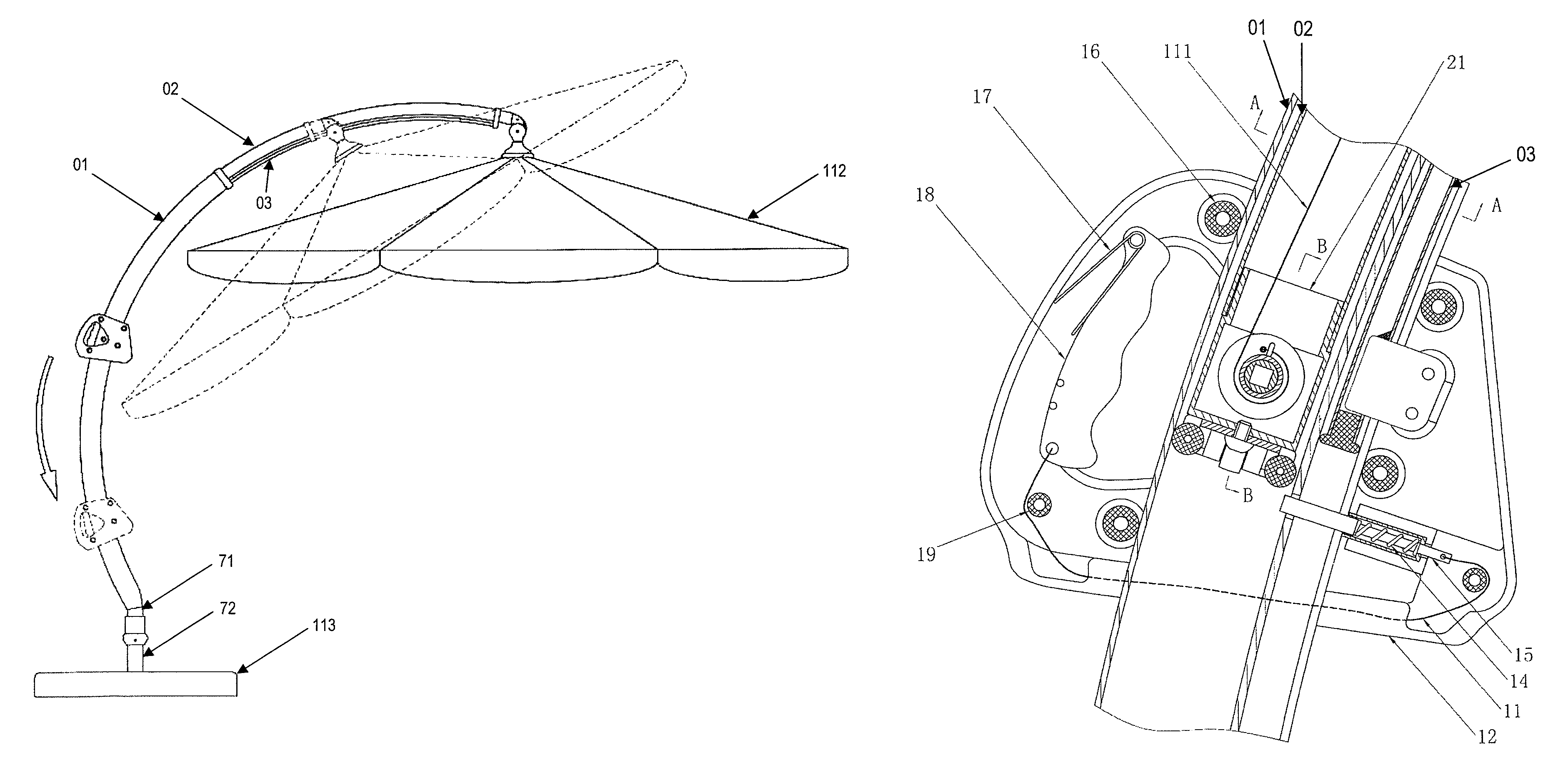
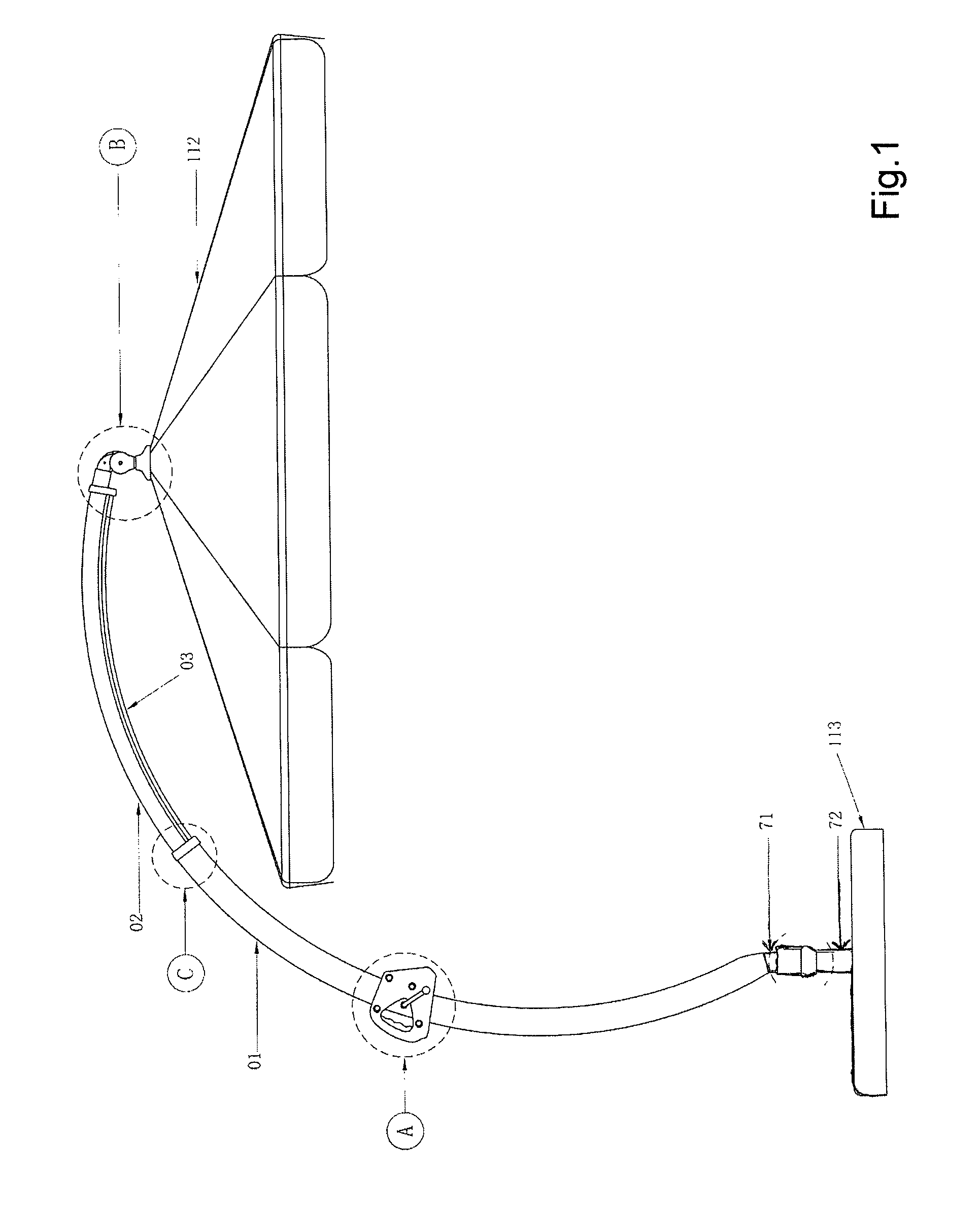
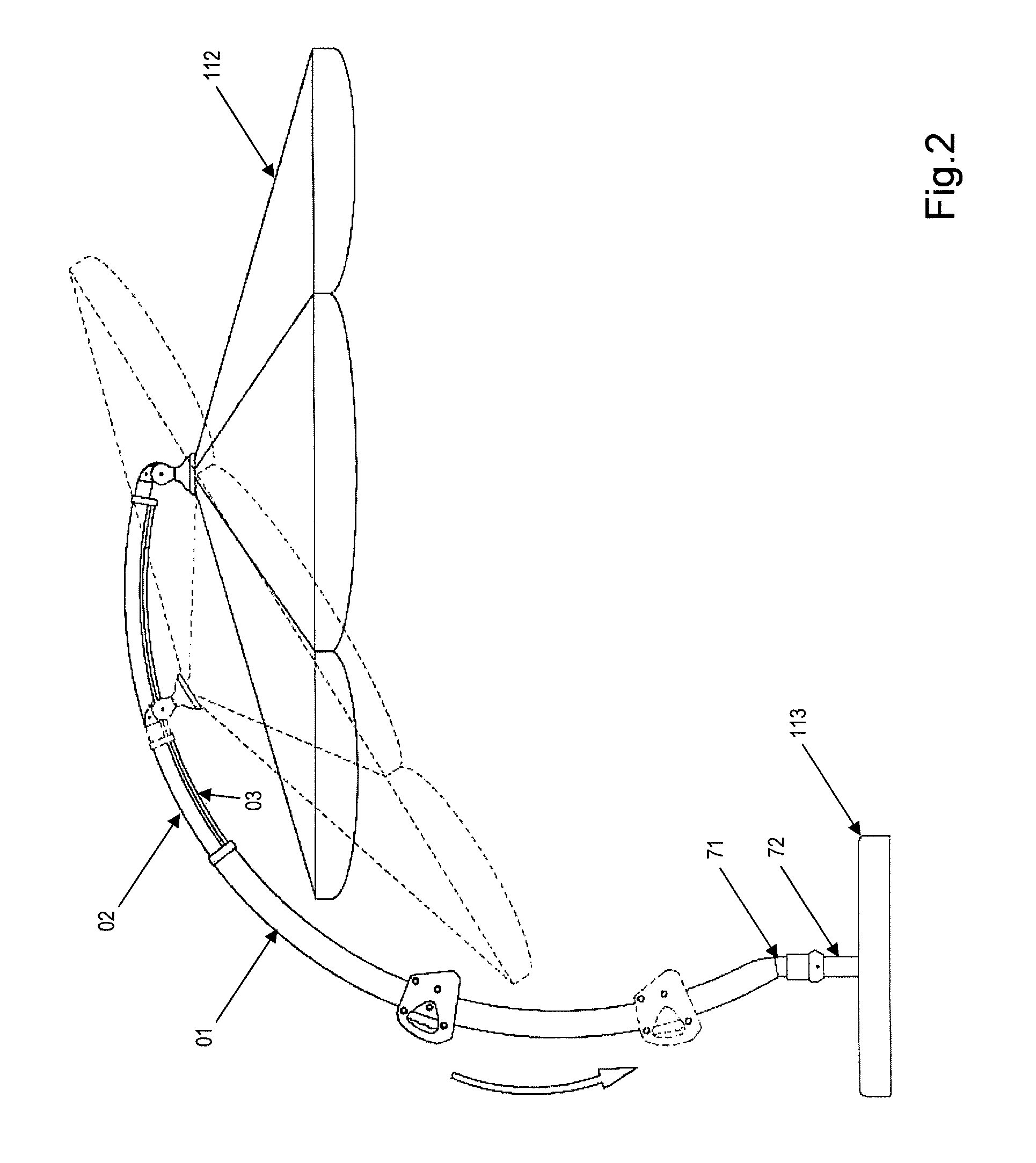
[0044]FIG. 1 shows an exemplary embodiment of a telescoping umbrella according to the invention in a side view. The umbrella shown is a so-called hanging umbrella, in which the canopy 112 is radially spaced apart from the foot 113 using an arched support construction. The support construction essentially comprises the receiving tube 01, which is curved in the form of a circular arc, and in which the telescope tube 02, which is also curved in the form of a circular arc, is situated so it is displaceable and lockable. In the exemplary embodiment shown here, the receiving tube 01 is connected fixed to the rotating mast 71, which is used as an adapter, and which is mounted so it is rotatable (in the horizontal plane) relative to the standing mast 72. The standing mast 72 is in turn connected fixed to the foot 113. The canopy 112 is linked on at the upper end—i.e., the end facing toward the canopy 112—of the telescope tube 02. A support tube 03 is situated parallel to the telescope tube ...


PUM


Abstract

The invention relates to a telescoping umbrella, particularly a sun or rain umbrella, having a receiving tube and a telescoping tube displaceably and lockably located therein, having an umbrella roof connected to the telescoping tube in an articulating manner, the umbrella roof being adjustable by means of a cable or Bowden wire running inside the tubes, and having an actuating device for the cable or Bowden wire, characterized in that the actuating device comprises a winch for the cable or Bowden wire, the winch being located inside the receiving tube.

Description

BACKGROUND OF THE INVENTION[0001]1. Field of the Invention[0002]The invention relates to a telescoping umbrella, in particular a parasol or rain umbrella, having a receiving tube and a telescoping tube situated therein so it is displaceable and lockable, having a canopy linked to the telescope tube, the canopy being adjustable using a cable pull or Bowden cable running inside the tubes, and having an actuating unit for the cable pull or Bowden cable.[0003]2. Description of Related Arts[0004]Umbrellas of the type under discussion have been known for many years from the leisure and garden field. Through their telescoping implementation, the canopy linked on the telescope tube may be brought into various positions in these umbrellas and locked there, whereby, on the one hand, upon usage of the umbrella, adaptability to different sun positions, wind directions, or the like is achieved. On the other hand, the umbrella may be collapsed easily to a small size when not in use, so that it ma...

Claims


Application Information

Patent Timeline
IPC IPC(8): A45B17/00A45B25/00
CPCA45B19/04A45B23/00A45B2023/0081A45B2023/0037A45B2023/0062A45B25/14
Inventor WANG, ZHONGLINLIU, KAI
Owner ZHEJIANG YOTRIO GRP CO LTD
Why Eureka
Try Eureka