Leak detector with a leak detector testing device

a leak detector and leak detector technology, applied in the field of leak detectors, can solve problems such as pressure loss of test gas

Active Publication Date: 2012-02-21
INFICON GMBH
View PDF22 Cites 5 Cited by
  • Summary
  • Abstract
  • Description
  • Claims
  • Application Information

AI Technical Summary

Benefits of technology

[0009]According to the disclosure, the test leak device is provided with a processor of its own, so as to reduce the number of connection lines to the base appliance and to enhance the properties of the sensors in the sub-housing. The processor processes the incoming data and performs a correction on the data, if need be. Preferably, the processor also causes a modulation of the light barrier signal, so that it becomes possible to separate the light barrier signal from noise signals. Thereby, the influence of interfering other light sources and the influence of the light being damped by dirt can be reduced substantially. Further, the signal is filtered, whereby an additional improvement of the signal reliability is obtained.
[0010]The test leak flow is highly temperature-dependent. For an exact determination of the temperature, a zero correction and an amplification correction of the signal of a temperature sensor should be performed. The values required may be stored in a data memory that could also be housed in the test leak device. The accuracy of the temperature measurement is enhanced and the effects of production spread are reduced.
[0012]In a preferred development of the disclosure, the plug-in channel includes a tube sealed from the outside against the environment of the test gas supply. The tube defines the circumferentially closed plug-in channel and forms the only way for the test gas to escape. This increases the outlet accuracy of the leakage flow coming from the test leak device, since no side flow paths are formed. Moreover, this impedes the intrusion of dirt into the test leak device, be it by the settlement of dust or by dirt introduced along with the sniffer probe.
[0014]The test leak device can thus be used optionally in the inserted state or in the removed state. In the inserted state, there is an advantage that the user only has to transport and handle a single appliance, i.e. the base appliance. The removed state offers the advantage that the test leak can be moved to a position favourable for the user, regardless of the position the stationary base appliance is in. Thus, the sub-housing is mobile with respect to the housing of the base appliance, yet it can be fastened to the housing of the base appliance such that the stand-alone mobility is given up. The test leak device forms a unit removable from the base appliance, comprising interface wires or a radio link as a bidirectional data channel for data communication with the base appliance.
[0015]According to another embodiment of the disclosure, it is provided that the plug-in channel has a radiation barrier with a radiation emitter and a radiation receiver, which are situated on different sides of the plug-in channel, and that the tube is made of material permeable to radiation. Preferably, the radiation barrier is a light barrier and the tube is transparent. The tube may be made of glass or plastic material. It receives the sniffer probe in the longitudinal direction and is light-transmissive in the transverse direction. On the one hand, the transparent tube avoids the deposition of accretions in the region of the light beam and, furthermore, it prevents test gas to enter into the appliance or the housing of the test leak device. The test gas can thus only prevail in the area intended for that purpose and can not expand inside the appliance in the area of the electronics.

Problems solved by technology

Here, “ageing” means the pressure loss of the test gas for leaks that do not operate at saturation vapor pressure.

Method used


Image

  • Leak detector with a leak detector testing device
  • Leak detector with a leak detector testing device
  • Leak detector with a leak detector testing device

Examples


Embodiment Construction

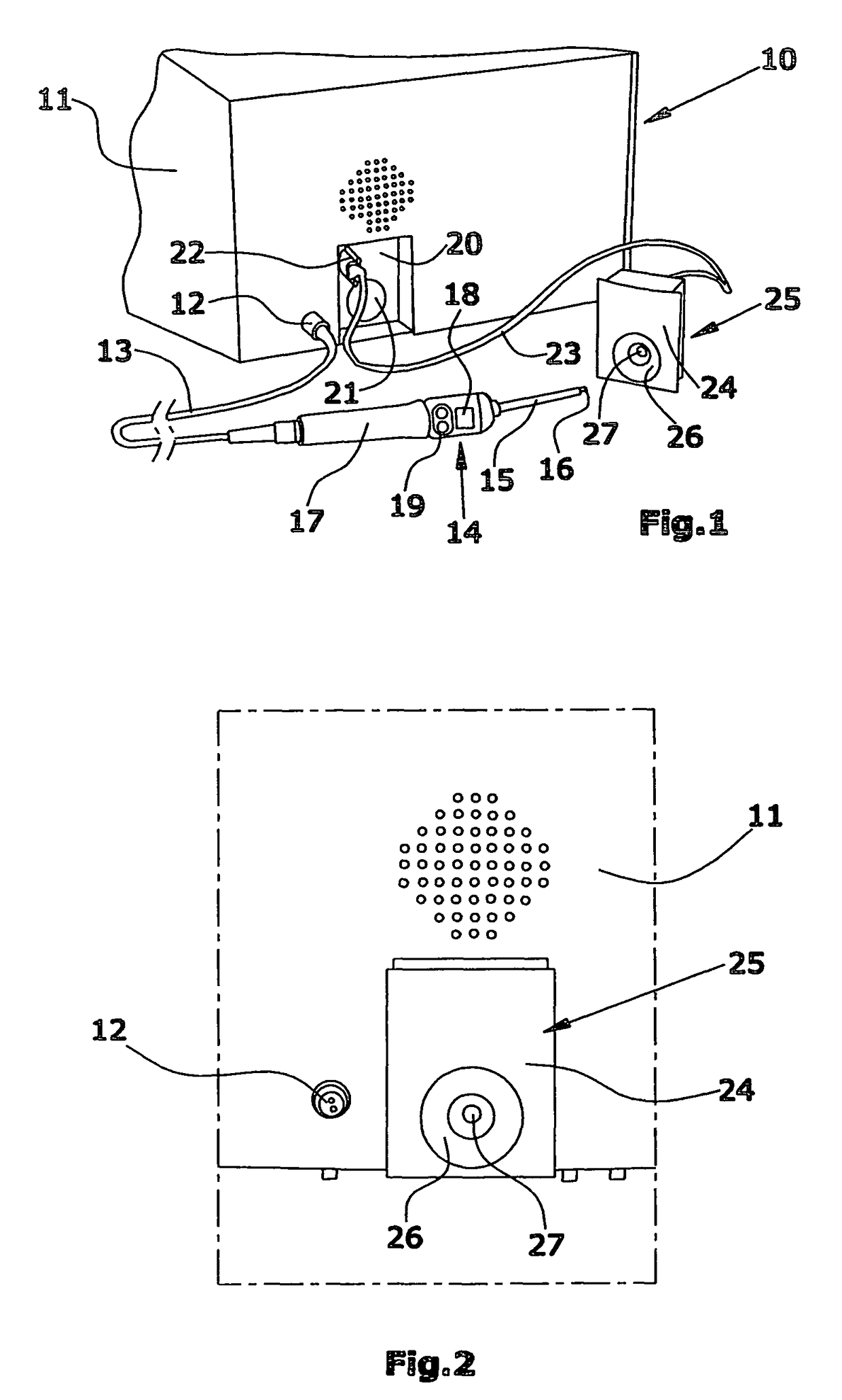
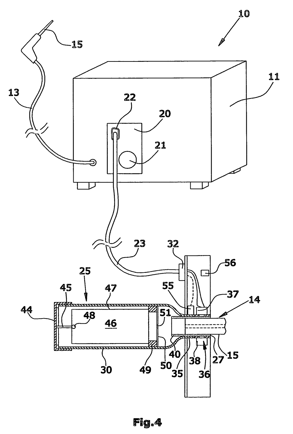
[0022]Referring now to FIG. 1, the leak detector comprises a base appliance 10 with a housing 11. The base appliance 10 includes all components necessary for leak detection and test gas detection, such as a vacuum pump, a test gas detector and a control device, as well as the required auxiliary aggregates. These are described in detail in WO 02 / 084246 A2 and in DE 103 08 687 A1.

[0023]As illustrated in FIG. 1, the housing 11 has a plug socket 12 for the line 13 of a sniffer probe 14. The mobile sniffer probe 14 is provided with a rod-shaped sniffer tip 15 having a suction opening 16 at its end. The sniffer probe 14 further comprises a handle 17, a display 18 as well as control keys 19. A hose lumen also extends through the line 13, which lumen connects the suction opening 16 with the suction source present in the housing 11.

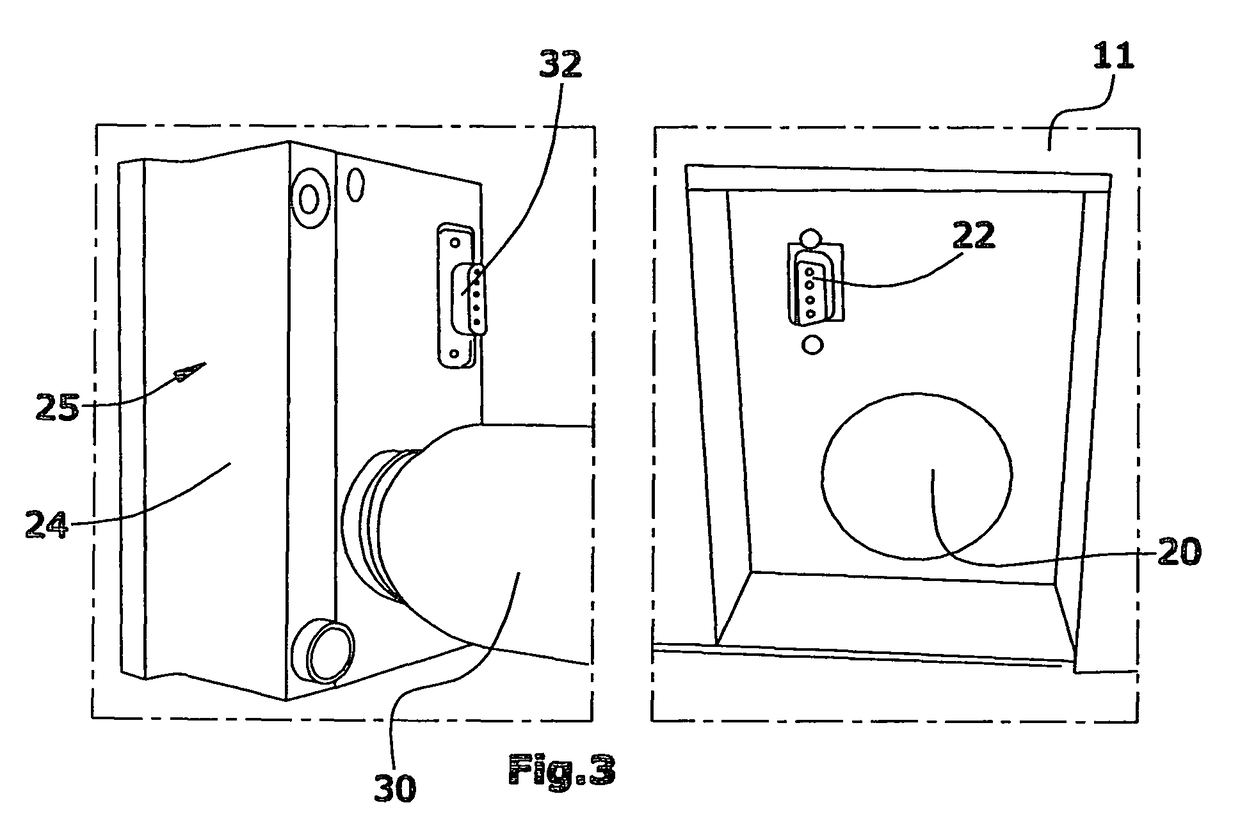
[0024]Further, the front face of the housing 11 is provided with a receptacle 20. This may be an indentation or a recess open to the front. In the recess 20, a tu...


PUM


Abstract

A leak detector comprising a base appliance provided with a gas detector, a vacuum pump, and a control device. A sniffer probe is connected to the base appliance. A test leak device containing the supply of test gas is arranged in a separate sub-housing. The sub-housing also contains a temperature sensor, a processor, and a data memory. The processor corrects the measured temperature according to a sample, and modulates the light of a light barrier. The processor is connected to the control device in the base appliance by a data cable.

Description

BACKGROUND[0001]1. Field of the Disclosure[0002]The disclosure refers to a leak detector with a base appliance comprising a vacuum pump, a test gas detector and a control device, a sniffer probe connected with a housing of the base appliance through a hose, and a sub-housing containing a test leak device by which a supply of test gas is discharged in a controlled manner into a plug-in channel for the sniffer probe.[0003]2. Discussion of the Background Art[0004]Test gas leak detectors are used in detecting leaks in containers, conduits and other test items. A cavity of the test item is filled with a test gas, and the leak detector is used to determine the presence of test gas in the ambient air outside the test item. Helium often is the test gas of choice. The leak detector includes a test gas detector adapted to selectively determine the presence of the test gas. Moreover, it is intended to obtain information about the rate at which the test gas leaks from the leak found, or the siz...

Claims


Application Information

Patent Timeline
Patent Type & Authority Patents(United States)
IPC IPC(8): G12B13/00G01M3/04
CPCG01M3/207
Inventor ROLFF, NORBERTROLFF, RANDOLFSEITZ, SANDRAGROSSE BLEY, WERNERBOEHM, THOMASWETZIG, DANIEL
Owner INFICON GMBH
Why Eureka
Try Eureka