Actuator assembly

a technology of actuators and parts, applied in the field of actuators, can solve the problems that the actuators are still susceptible to improvement, and achieve the effect of enhancing packaging and reducing the size of the actuator

Active Publication Date: 2012-02-21
DANA AUTOMOTIVE SYST GRP LLC
View PDF18 Cites 23 Cited by
  • Summary
  • Abstract
  • Description
  • Claims
  • Application Information

AI Technical Summary

Benefits of technology

[0007]The actuator assembly in accordance with the present invention provides an exceptionally compact source for hydraulic fluid pressure in a convenient packaging.

Problems solved by technology

While known fluid actuators, including but not limited to those discussed above, have proven to be acceptable for various applications, such actuators are nevertheless susceptible to improvements that may reduce their size and enhance packaging.

Method used


Image

  • Actuator assembly
  • Actuator assembly
  • Actuator assembly

Examples


Embodiment Construction

[0012]The preferred embodiment of the present invention will now be described with the reference to accompanying drawings.

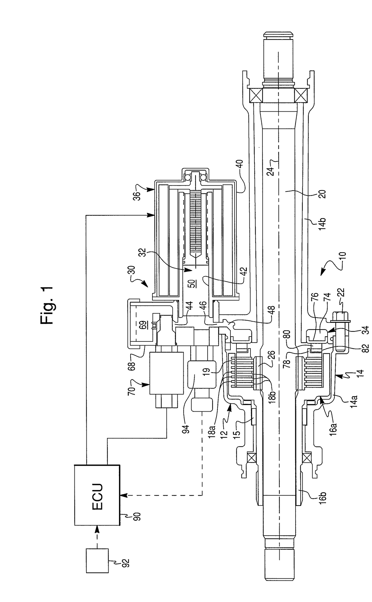
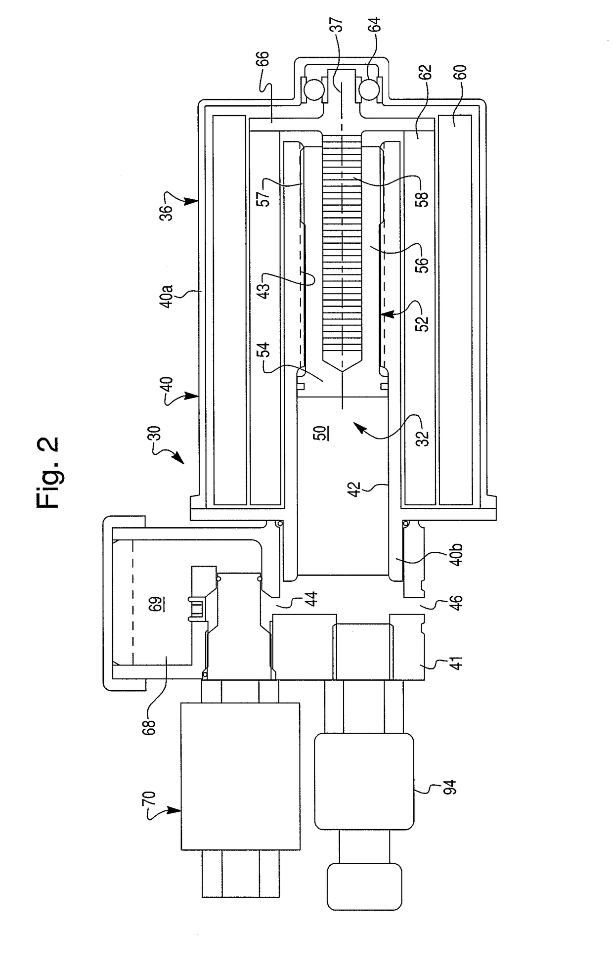
[0013]FIG. 1 of the drawings illustrates a torque coupling apparatus 10 in accordance with a first exemplary embodiment of the present invention. As illustrated, the torque coupling apparatus 10 comprises a first device in the form of a friction clutch assembly 12 and a fluid actuator assembly 30 provided for selectively actuating the friction clutch assembly 12.

[0014]Preferably, the friction clutch assembly 12 is rotatably supported within a coupling housing 14 through anti-friction bearing 15 for rotation about a longitudinal axis 24. The friction clutch assembly 12 includes an input member in the form of a clutch carrier member 16, and output member in the form of a drive shaft 20, and a clutch pack 18 defined by two sets of alternating outer, or first, friction clutch members 18a and inner, or second, friction clutch members 18b. The coupling housing 14 inclu...


PUM


Abstract

An actuator assembly for generating a fluid pressure and applying the fluid pressure to a first device. The actuator assembly comprises a first fluid chamber and a first piston disposed adjacent to the first fluid chamber, a second fluid chamber and a second piston slidably received in the second fluid chamber, a fluid passage connecting the first fluid chamber with the second fluid chamber, and an actuator motor for selectively reciprocating the first piston so that axial movement of the first piston generates a fluid pressure within the first fluid chamber. The first piston is disposed within the actuator motor. As the first chamber is fluidly communicating with the second fluid chamber, the linear motion of the first piston causes corresponding linear motion of the second piston for applying the fluid pressure to the first device.

Description

BACKGROUND OF THE INVENTION[0001]1. Field of the Invention[0002]The present invention relates to actuators in general, and more particularly to an actuator assembly including a fluid pressure generating piston assembly disposed in an actuator motor.[0003]2. Description of the Prior Art[0004]Fluid actuators are widely employed in various applications as a source of a pressurized hydraulic fluid, such as friction clutch assemblies and hydraulic brake systems. Especially popular are hydraulic actuators driven by an electric motor. These actuators, typically, include a motor driven screw shaft, a non-rotatable nut threaded to the screw shaft, and a hydraulic piston slidably mounted within a hydraulic cylinder and fixed to the nut. When the electric motor is actuated, the rotary motion of the screw shaft is transmitted to the nut that linearly travels along the screw shaft. Since the piston is fixed to the nut, it also moves along the screw shaft, thus generating a desired hydraulic pres...

Claims


Application Information

Patent Timeline
Patent Type & Authority Patents(United States)
IPC IPC(8): F04B9/00
CPCF16D29/005Y10T74/18056
Inventor KRISHER, JAMES A.
Owner DANA AUTOMOTIVE SYST GRP LLC
Why Eureka
Try Eureka