Safety device for a syringe

Active Publication Date: 2012-02-21
TECH GRP EURO LTD
View PDF7 Cites 11 Cited by
  • Summary
  • Abstract
  • Description
  • Claims
  • Application Information

AI Technical Summary

Benefits of technology

[0009]The purpose of the present invention is to further improve the state of the aforementioned art, by making it possible to manufacture the skirt of the plunger assembly for lower-cost and assure the safe release of the one or more retaining tabs by this skirt at the end of the injection, while also allowing the radial dimensions of the device to be as small as possible.
[0010]This purpose is achieved because of the fact that the proximal end portion of the support sleeve has at least one deflection ramp suitable, at the end of the plunger assembly stroke, of engaging with said skirt for deforming the skirt so as to bring a portion of said skirt closer to the actuating part of the retention tab to enhance the engagement between the skirt and the actuating part.
[0012]In contrast to EP 1,235,603, the skirt can have reduced radial dimensions so as to allow the actuation of the device, meaning the relative movement of the protection sleeve and the support sleeve, without the one or more retention tabs extending a large distance from the axis of the device, nor in particular around a collar that the syringe body could have.
[0014]This position makes it possible to assure that the deformation of the skirt of the plunger assembly needed for the release of the retention tab is achieved in the right area.
[0016]This constitutes a simple means for implementing the deflection ramp.
[0019]In fact, despite the fact that this tab is at least partially “masked” by the bulk of the collar, it is accessible for the skirt because of the deformation thereof achieved by the deflection ramp. This makes it possible to considerably reduce the radial dimensions of the device.

Problems solved by technology

However, this contact results reliably from the presence of the deflection ramp.

Method used


Image

  • Safety device for a syringe
  • Safety device for a syringe
  • Safety device for a syringe

Examples


first embodiment

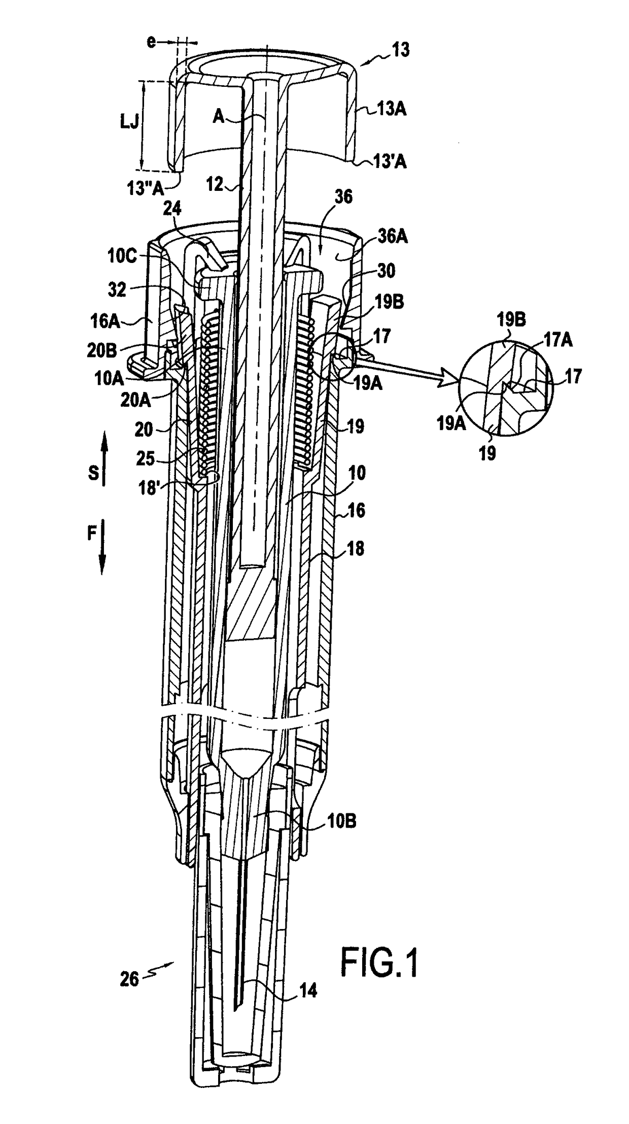
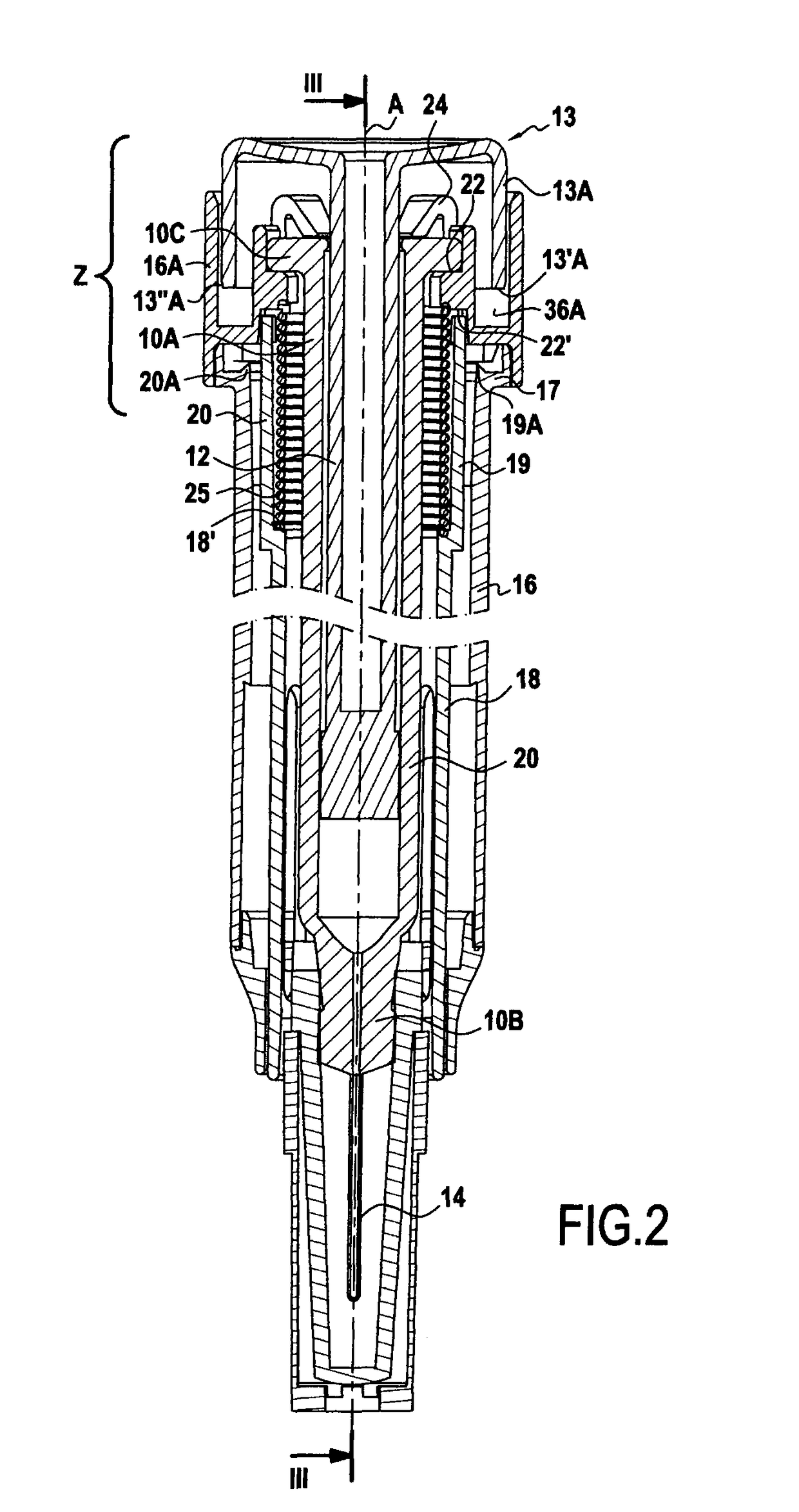
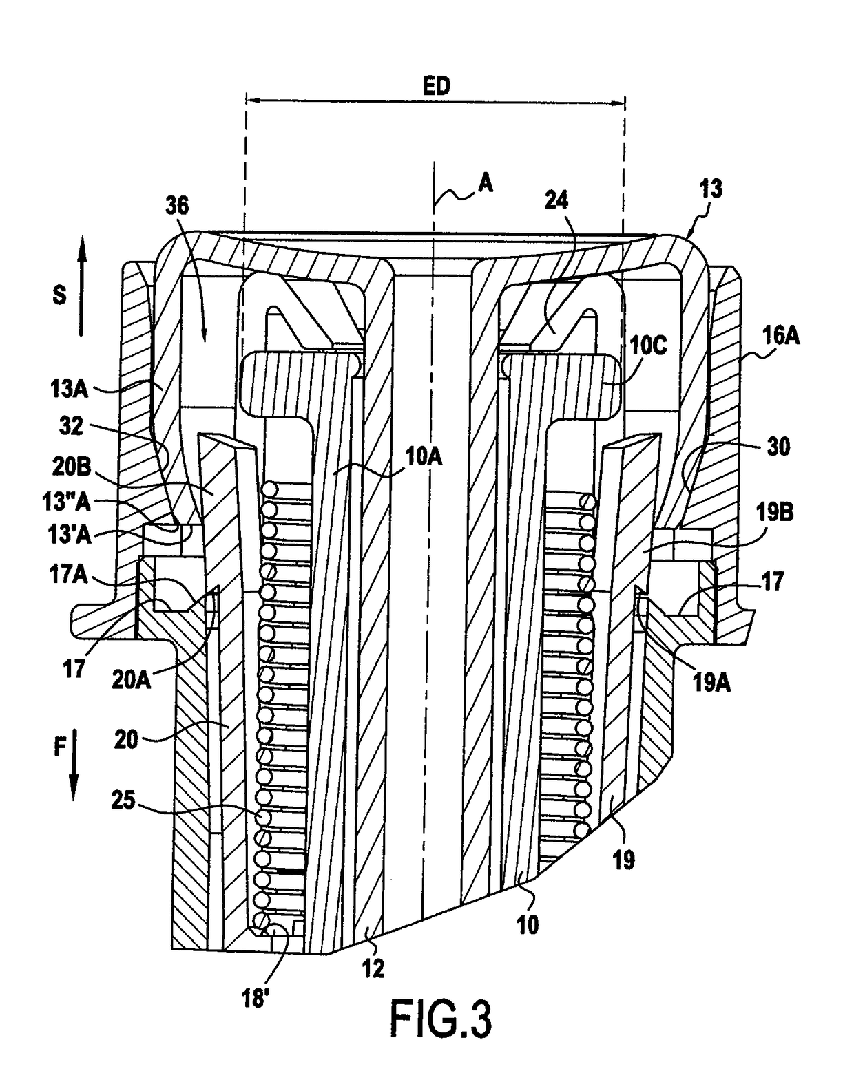
[0031]The safety support device for the syringe includes, a support sleeve 16 and a protection sleeve 18 which is fitted into the support sleeve 16 and arranged to be able to slide relative to the support. In the ready position before the injection, the protection sleeve 18 is retained inside the support sleeve 16 by two retaining tabs, respectively 19 and 20, which are rigidly connected to the protection sleeve 18 and are retained relative to the support sleeve 16. In fact, these tabs are positioned to be able to latch onto a shoulder 17 which the support sleeve has in the area of its proximal end 16A. For this purpose the tabs have a projection, respectively 19A and 20A, which latch onto the rim of the shoulder 17. As can be seen better in FIG. 1, the rim 17A projects slightly in the direction S, going from the distal end towards the proximal end, so as to form a retention rib. The projections from the tabs and the rim have the shape of ramps inclined upwards to make the latching...

second embodiment

[0044]Now the second embodiment from FIG. 5 will be described. On the left half of this figure, the device is shown while injecting, while the retaining tabs are in the retained position, whereas in the right half, the retention tabs are being released.

[0045]In this embodiment, the support sleeve 116 is arranged inside of the protection sleeve 118. The syringe body is retained relative to the support sleeve because of the fact that the collar 10C of this body is retained between a shoulder 122 turned towards the proximal end and a latching rib or analogue 124 spaced from the shoulder. The shoulder and the rib are rigidly connected to the sleeve 116 and, more specifically, are located at the proximal end 116A thereof. The restoring spring 125 is arranged between the supporting surface 122′ which is fixed relative to the sleeve 116 and is made up by the opposite surface of the shoulder 122, and the supporting surface 118′ which is fixed relative to the protection sleeve 118 and is tur...


PUM


Abstract

The invention relates to a safety device comprising a supporting sleeve (16) for holding the syringe body (10), a protective sleeve (18), and at least one holding tongue (19, 20) which is rigidly connected to the protection sleeve and can be held by the supporting sleeve (16), in the holding position. The piston comprises a cylindrical skirt (13A) that can end up facing a part of the proximal end (16A) of the supporting sleeve, at the end of the injection stroke, in order to co-operate with an actuating part (19B, 20B) of the holding tongue, and to release same in such a way as to enable a relative sliding of the protection sleeve and the supporting sleeve in order to protect the neddle. This proximal end part (16A) has at least one deflection ramp (30, 32) that can co-operate with the skirt (13A), at the end of the piston stroke, in order to deform the skirt in such a way as to bring part of the skirt of the actuating part (19B, 20B) closer to the holding tongue (19, 20).

Description

CROSS-REFERENCE TO RELATED APPLICATIONS[0001]This application is a Section 371 of International Application No. PCT / FR2008 / 051907, filed Oct. 22, 2008, which was published in the French language on May 7, 2009 under International Publication No. WO 2009 / 056734 A2 and the disclosure of which is incorporated herein by reference.BACKGROUND OF THE INVENTION[0002]The present invention relates to a safety device for a syringe which has a syringe body, a plunger assembly and a needle, where the device includes a support sleeve suitable for retaining the body of the syringe relative thereto, a protection sleeve and at least one retaining tab rigidly connected to the protection sleeve and suitable for occupying a retained position in which the tab is retained relative to the support sleeve and a released position in which said tab stops being retained relative to the support sleeve to allow relative sliding of the protection sleeve and the support sleeve towards a protection position in whic...

Claims


Application Information

Patent Timeline
Patent Type & Authority Patents(United States)
IPC IPC(8): A61M5/32
CPCA61M5/326A61M5/3202A61M2005/3264A61M2005/3261A61M2005/3247
Inventor CHEVALLIER, STEPHANECHEVALLIER, JEAN-MICHEL
Owner TECH GRP EURO LTD
Why Eureka
Try Eureka