Spindle motor and disk drive apparatus

a technology of spindle motor and disk drive, which is applied in the direction of windings, recording information storage, instruments, etc., can solve the problems of rigid base and defective thin insulating layer of conducting wire, and achieve the effect of reducing the thickness of the spindle motor in the axial direction

Active Publication Date: 2012-02-21
NIDEC CORP
View PDF12 Cites 44 Cited by
  • Summary
  • Abstract
  • Description
  • Claims
  • Application Information

AI Technical Summary

Benefits of technology

[0010]According to the above-described preferred embodiment of the present invention, the circuit board is arranged at a portion on the outer side in the radial direction and above the bottom portion, such that the thickness of the spindle motor in the axial direction will be reduced. Further, according to the above-described preferred embodiment of the present invention, an electrical contact between the conducting wire and the opening edge portion will be prevented.

Problems solved by technology

However, when the size in the axial direction of the base is reduced, the base consequently becomes thinner which acts to decrease the rigidity of the base.
However, this procedure leads to the thin insulating layer of the conducting wire becoming defective due to the contact between the conducting wire and the base.

Method used


Image

  • Spindle motor and disk drive apparatus
  • Spindle motor and disk drive apparatus
  • Spindle motor and disk drive apparatus

Examples


Embodiment Construction

[0019]Preferred embodiments of the present invention will now be described in detail with reference to FIGS. 1 through 7. Note that the terms “axial direction”, “axial”, and “axially” as used herein refer to a direction parallel or substantially parallel to a central axis J, whereas the terms “radial direction”, “radial”, and “radially” as used herein refer to directions perpendicular or substantially perpendicular to the central axis J. Also note that it is assumed herein that a side at which a coil is arranged with respect to a base member is defined as an upper side along the central axis. Note, however, that the central axis may not necessarily be parallel or substantially parallel to the direction of gravity in actual practice.

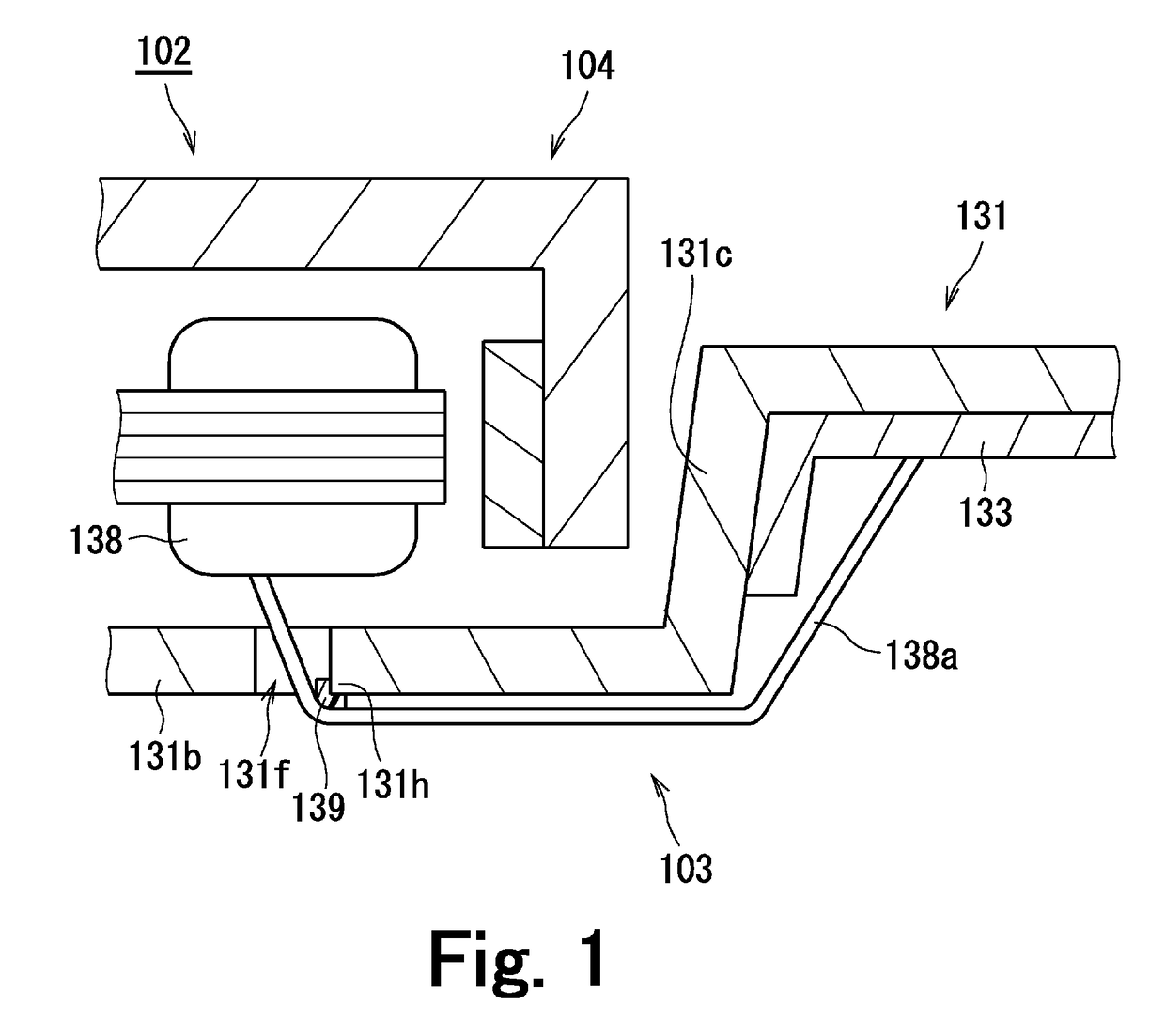
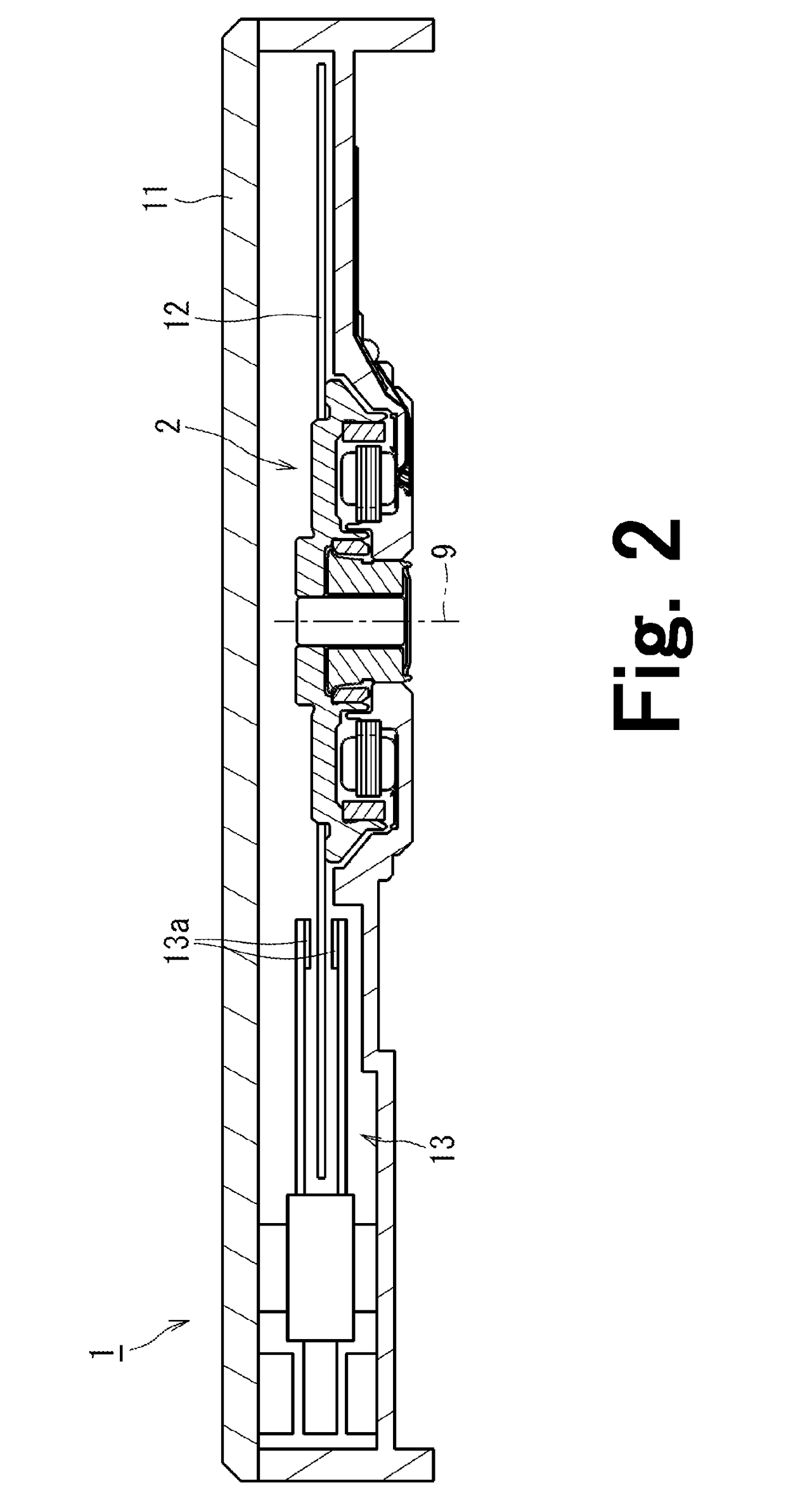
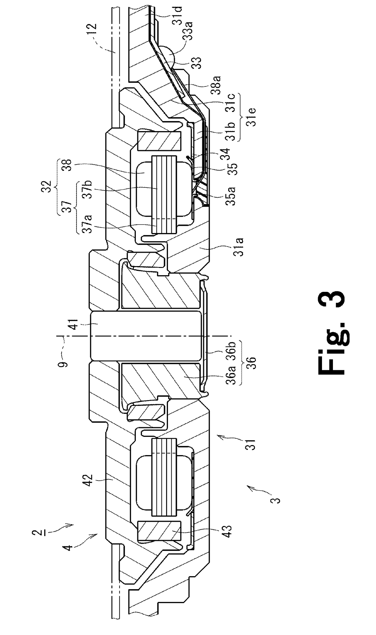
[0020]FIG. 1 is a schematic partial section view of a spindle motor 102 according to a preferred embodiment of the present invention. As shown in FIG. 1, the spindle motor 102 preferably includes a stator portion 103 and a rotor portion 104. The rotor por...


PUM

PropertyMeasurementUnit
thicknessaaaaaaaaaa
voltageaaaaaaaaaa
voltageaaaaaaaaaa

Abstract

A stator portion of a spindle motor includes a substantially cup-shaped base member including a bottom portion expanding in a radial direction, and a wall portion extending upwards from an outer edge portion of the bottom portion. A circuit board is fixed to a lower surface of the base member in a position on the outer side in the radial direction and on the upper side than the bottom portion. Accordingly, the thickness of the spindle motor in the axial direction can be reduced. The base member has a through hole formed axially through the bottom portion. An opening edge portion of the base member is covered with the insulating layer. A conducting wire from a coil is drawn through the through hole, led out along the surface of the insulating layer, and connected to the circuit board positioned on the outer side in the radial direction than the bottom portion. Accordingly, the conducting wire can be led to the circuit board while the electric connection between the conducting wire and the opening edge portion can be prevented.

Description

BACKGROUND OF THE INVENTION[0001]1. Field of the Invention[0002]The present invention relates to a spindle motor and a disk drive apparatus.[0003]2. Description of the Related Art[0004]In hard disk drives and in optical disk drives, spindle motors arranged to rotate a disk around a center axis are typically used. These spindle motors include a stator portion fixed to a housing of an apparatus and a rotating portion arranged to support and rotate the disk. The spindle motors generate a torque around the center axis through the use of a magnetic flux generated between the stator portion and a rotating portion, to thereby rotate the rotating portion with respect to the stator portion.[0005]The stator portion typically includes a coil arranged to generate the magnetic flux and an end of the wire of the coil is led to the outside of the spindle motor and connected to a predetermined circuit board. For example, Japanese Laid-Open Patent Publication No. 2005-210787 describes, in paragraph ...

Claims


Application Information

Patent Timeline
Patent Type & Authority Patents(United States)
IPC IPC(8): G11B33/12H02K5/22
CPCH02K3/50H02K5/225H02K2211/03H02K11/0073H02K11/33
Inventor SEKII, YOICHIYAWATA, ATSUSHI
Owner NIDEC CORP
Why Eureka
Try Eureka