Method of correction of acoustic parameters of electro-acoustic transducers and device for its realization

a technology of electro-acoustic transducers and acoustic parameters, applied in the field of acoustics, can solve the problems of poor quality of correction, low measurement precision, and devices that do not differentiate and separate direct sound waves, and achieve the effects of increasing the validity of automatic correction, improving the playback quality of acoustic signals, and improving accuracy and speed of correction

Active Publication Date: 2012-02-21
REAL SOUND LAB SIA
View PDF20 Cites 13 Cited by
  • Summary
  • Abstract
  • Description
  • Claims
  • Application Information

AI Technical Summary

Benefits of technology

[0012]It is an object of the present invention is to overcome the above described shortcomings of the conventional technical solutions and to increase playback quality of acoustic signal of various electro-acoustic transduc

Problems solved by technology

Disadvantage of the known technical solutions is relatively low precision of measuring and poor quality of correction results.
Up to now used measuring devices do not differentiate and separate direct sound waves and early reverberation of sound waves from posterior reverberation of sound waves.
The conventional technical solutions for correction of acoustic parameters of electro-acoustic transducer that are based on evaluation results of sound pressure caused by electro-acoustic transducer do not reflect real problems of playback of electro-acoustic transducer.
Hence, the operator using the conventional technical solution faces an insoluble problem of having to select which of acquired sound pressure frequency responses to be used and which of parameters additionally to be corrected manually or to be processed differently.
Furthermore, using these measuring results for correction of acoustic parameters of electro-acoustic transducer, new sound distortions are created because there is attempt to correct the interference expression of sound waves in certain place of the room in known technical solutions.
Thus, that kind of correction of acoustic parameters of electro-acoustic transducer is incorrect and inadequate to eliminate the transmission distortions and irregularities of electro-acoustic transducer.
Disadvantage of the given method lies in th

Method used


Image

  • Method of correction of acoustic parameters of electro-acoustic transducers and device for its realization
  • Method of correction of acoustic parameters of electro-acoustic transducers and device for its realization
  • Method of correction of acoustic parameters of electro-acoustic transducers and device for its realization

Examples


Embodiment Construction

[0039]In an exemplary embodiment of the present invention, the correction of acoustic parameters of electro-acoustic transducer is made by the device described in FIG. 4 that comprises Measuring System 1 and at least one corrector 2, wherein Measuring System 1 comprises Measuring Section 3, the measurements processing section 4 and Interface Block 5, and corrector 2 comprises Control Section 6, and Realization Block 7. Sound Signal Input 8 goes into Realization Block 7, from which Sound Signal Output 9 is generated. The correction of acoustic parameters of electro-acoustic transducer is made by this exemplary embodiment as follows:

[0040]Schematically described Signal Source 10 (FIG. 5) with acoustic test signals written in memory repeatedly plays back acoustic test signal whose spectrum is balanced with interference spectrum in the site of measurements. Therefore, test signal is being chosen with higher energy spectrum in the lower frequency area, where the interference energy is hi...


PUM


Abstract

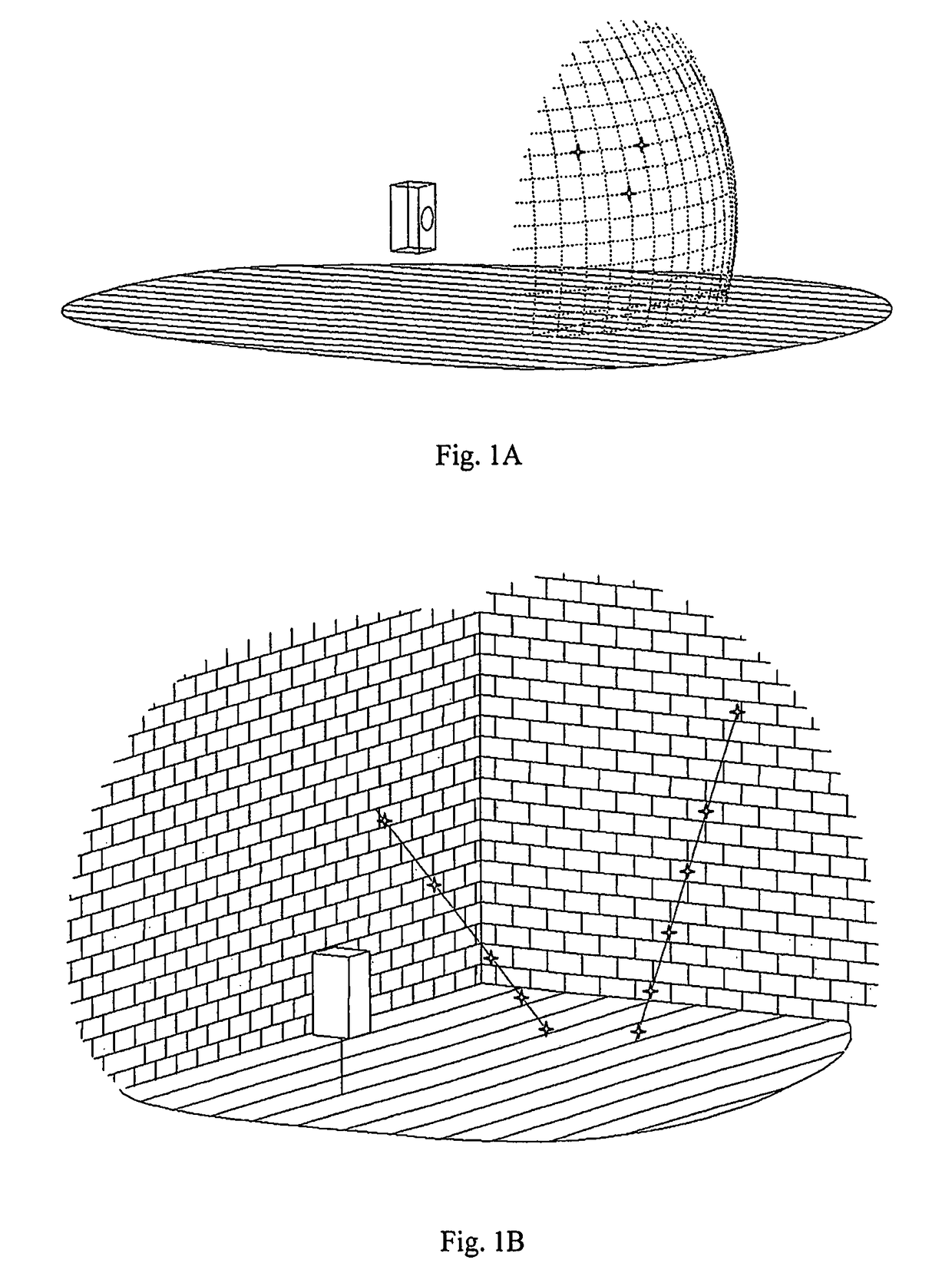
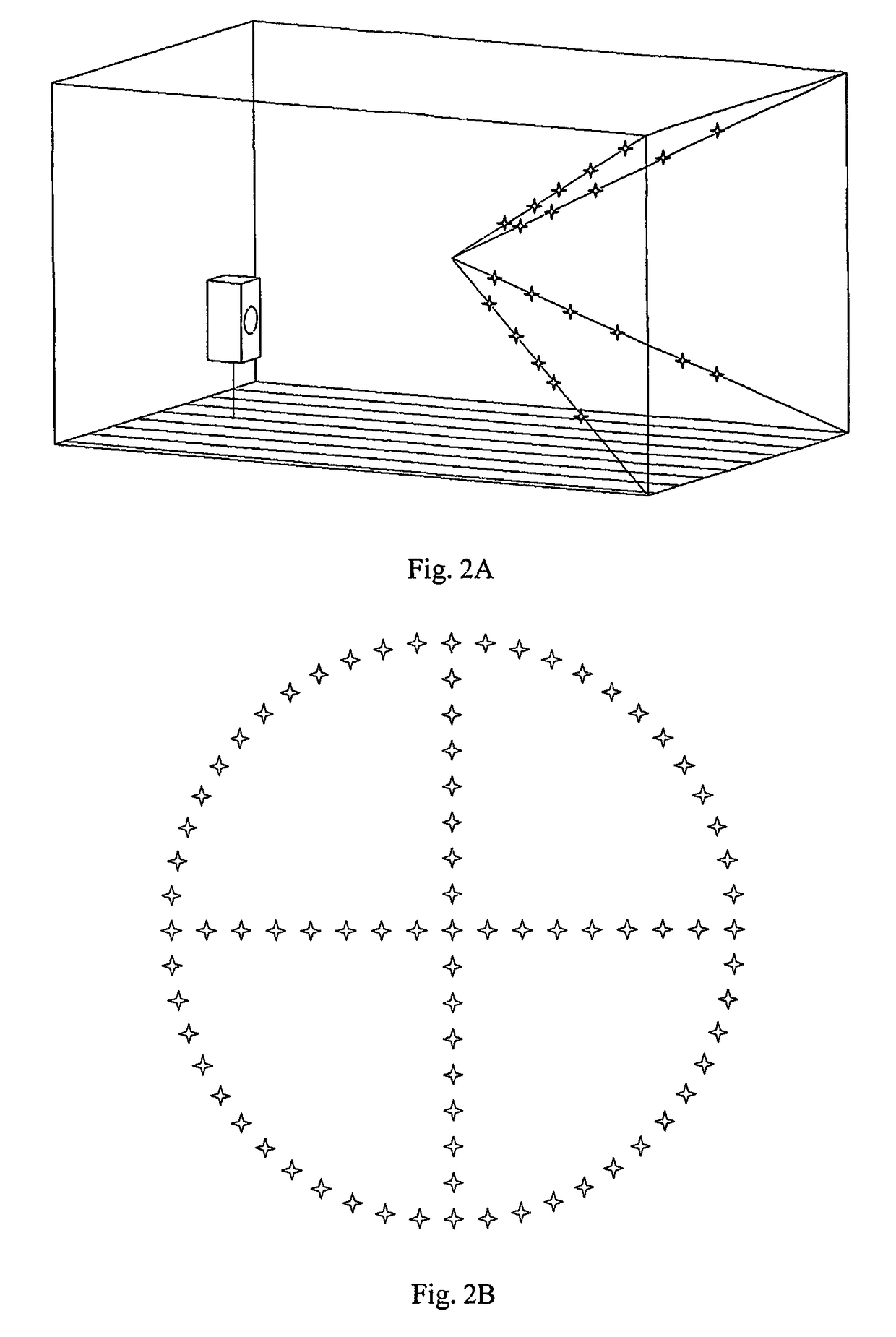
A device and method for improving the performance of an electro-acoustic transducer. An acoustic test signal is generated through the electro-acoustic transducer. The acoustic test signal is measured at multiple points on an ambient surface around the electro-acoustic transducer to create measured acoustic data. Based on the measured acoustic data, an acoustic power frequency response of the electro-acoustic transducer is calculated. A correction impulse response for the electro-acoustic transducer is determined based on the acoustic power frequency response. A correction filter applies the correction impulse response to a sound signal input to generate a sound signal output for playback through the electro-acoustic transducer.

Description

CROSS-REFERENCE TO RELATED APPLICATION[0001]This is a U.S. national stage entry under 35 U.S.C. §371 of International Application No. PCT / LV2005 / 000014, filed on Dec. 14, 2005 and published in English as International Publication No. WO 2006 / 123923 A1 under the Patent Cooperation Treaty, which claims priority to Latvian Application No. P-05-60, filed on May 18, 2005.FIELD OF INVENTION[0002]This invention relates to the field of acoustics, in particular to methods and devices of correction of acoustic parameters of electro-acoustic transducers and can be applied for improvement of playback parameters of acoustic signals of various electro-acoustic transducers.BACKGROUND[0003]There are known devices and methods for correction of acoustic parameters of electro-acoustic transducer by using measurements of acoustic parameters of electro-acoustic transducers where correction is performed both automatically and with participation of sound operator. Disadvantage of the known technical solut...

Claims


Application Information

Patent Timeline
IPC IPC(8): H04R29/00H03G1/00H03G5/16H04R3/04
CPCH03G1/0088H04R29/001H04R3/04
Inventor SKURULS, RAIMONDS
Owner REAL SOUND LAB SIA
Why Eureka
Try Eureka