Techniques and apparatus for the measurement of mutual inductance in a switched reluctance machine

a technology of mutual inductance and switch resistance, which is applied in the direction of electronic commutators, motor/generator/converter stoppers, dynamo-electric converter control, etc., can solve the problem of not being able to use high-performance systems such as military and aerospace applications

Active Publication Date: 2012-02-28
BOARD OF RGT THE UNIV OF TEXAS SYST
View PDF7 Cites 19 Cited by
  • Summary
  • Abstract
  • Description
  • Claims
  • Application Information

AI Technical Summary

Problems solved by technology

While these assumptions may be reasonable in a few industrial applications, they cannot be used for high performance systems, such as military and aerospace applications.

Method used


Image

  • Techniques and apparatus for the measurement of mutual inductance in a switched reluctance machine
  • Techniques and apparatus for the measurement of mutual inductance in a switched reluctance machine
  • Techniques and apparatus for the measurement of mutual inductance in a switched reluctance machine

Examples


Embodiment Construction

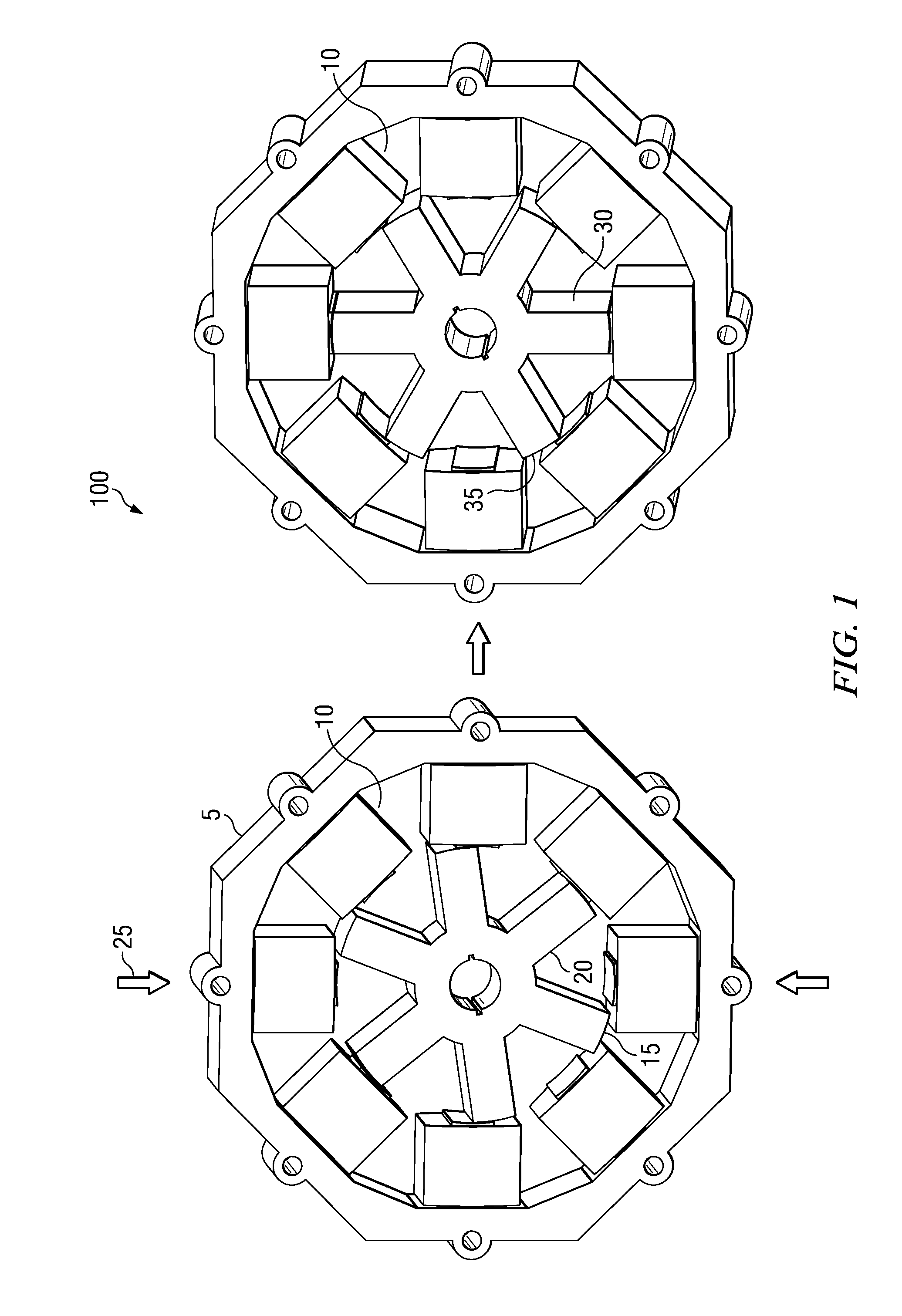
[0020]Referring to FIG. 1, a perspective diagram of a section of a Switched Reluctance Motor 100 (SRM). An SRM comprises of a stator 5 and a rotor 20. A stator comprises of several coils 10. In the example embodiment, the stator comprises eight coils. Also, in the example embodiment the rotor comprises six magnetic poles. This example embodiment is typically referred to as 8 / 6 SRM configuration. Apparently, several motor configurations are feasible in practice. The analysis and description herein generally refers to the 8 / 6 SRM configuration which can be adapted for other motor configurations.

[0021]Switched reluctance motors are often operated with a phase overlap, which results in higher torque and lower pulsation. A pattern of excitation in which there is a very low flux density between the excited phases is called “long flux path excitation (LFPE)”. The other excitation scheme is called “short flux path excitation (SFPE)” wherein the flux path closes its loop through the adjacent...


PUM


Abstract

A system and technique for measuring the mutual inductance in a switched reluctance machine (SRM). In a first example embodiment of the technique, a voltage pulse is applied to primary coil when the machine is stationery. By measuring current in the primary coil and measuring induced voltages in adjacent open circuited coils mutual inductance may be determined. In another example embodiment, a voltage pulse is applied to the primary coil when the machine is stationery. The secondary coil is allowed to freewheel current through the phase. By measuring time taken by the primary phase to reach a preset value, the mutual inductance for the known position of a rotor can be determined.

Description

[0001]This application claims priority under 35 U.S.C. 119(e)(1) of provisional application No. 60 / 936,127, filed on Jun. 16, 2007, incorporated herein by reference in its entirety.TECHNICAL FIELD OF THE INVENTION[0002]The present invention generally relates to motors, and more specifically to switched reluctance motors.BACKGROUND OF THE INVENTION[0003]Several mission critical products in military and aerospace applications require high-precision controllers on switched reluctance machines in order to function safely and properly. (“reluctance motor” and “reluctance machine” are used interchangeably). A majority of controllers in use today assume an ideal inductance profile while ignoring mutual effects. However, an ideal analytical model needs to incorporate up-to-date information about machine dynamics including a very accurate parameter identification and compensation technique.[0004]The design, control and analysis of a switched reluctance machines require detailed information a...

Claims


Application Information

Patent Timeline
Patent Type & Authority Patents(United States)
IPC IPC(8): H02P6/00
CPCG01R27/2611G01R31/34H02P25/083H02P25/089
Inventor FAHIMI, BABAKKRISHNAMURTHY, UMAMAHESHWAR
Owner BOARD OF RGT THE UNIV OF TEXAS SYST
Why Eureka
Try Eureka