
Transversal type filter

a filter and transversal type technology, applied in piezoelectric/electrostrictive/magnetostrictive devices, piezoelectric/electrostriction/magnetostriction machines, electrical apparatus, etc., can solve the problem of only applying this method, unable to realize the widening of the frequency pass band, and loss of energy, etc. problem, to achieve the effect of accurately designing the filter, suppressing the diffraction of the elastic wave output, and larg

Inactive Publication Date: 2012-02-28
NIHON DEMPA KOGYO CO LTD
View PDF22 Cites 0 Cited by
  • Summary
  • Abstract
  • Description
  • Claims
  • Application Information

AI Technical Summary

Benefits of technology

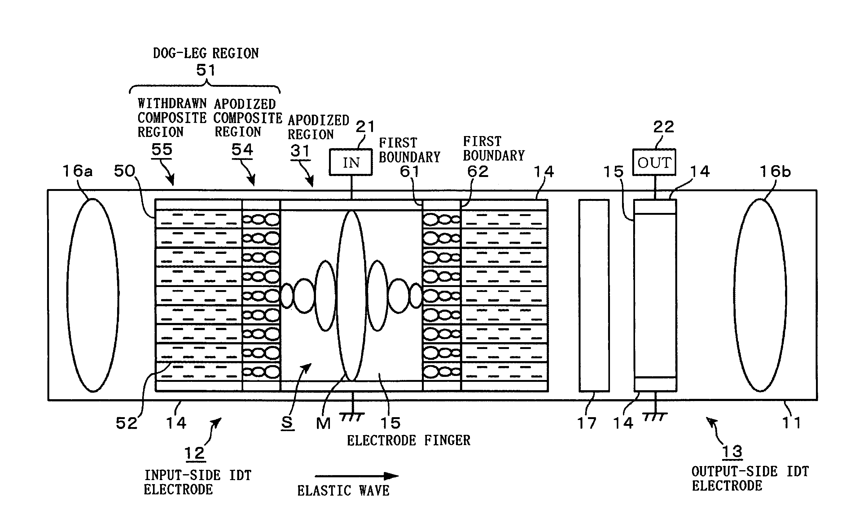
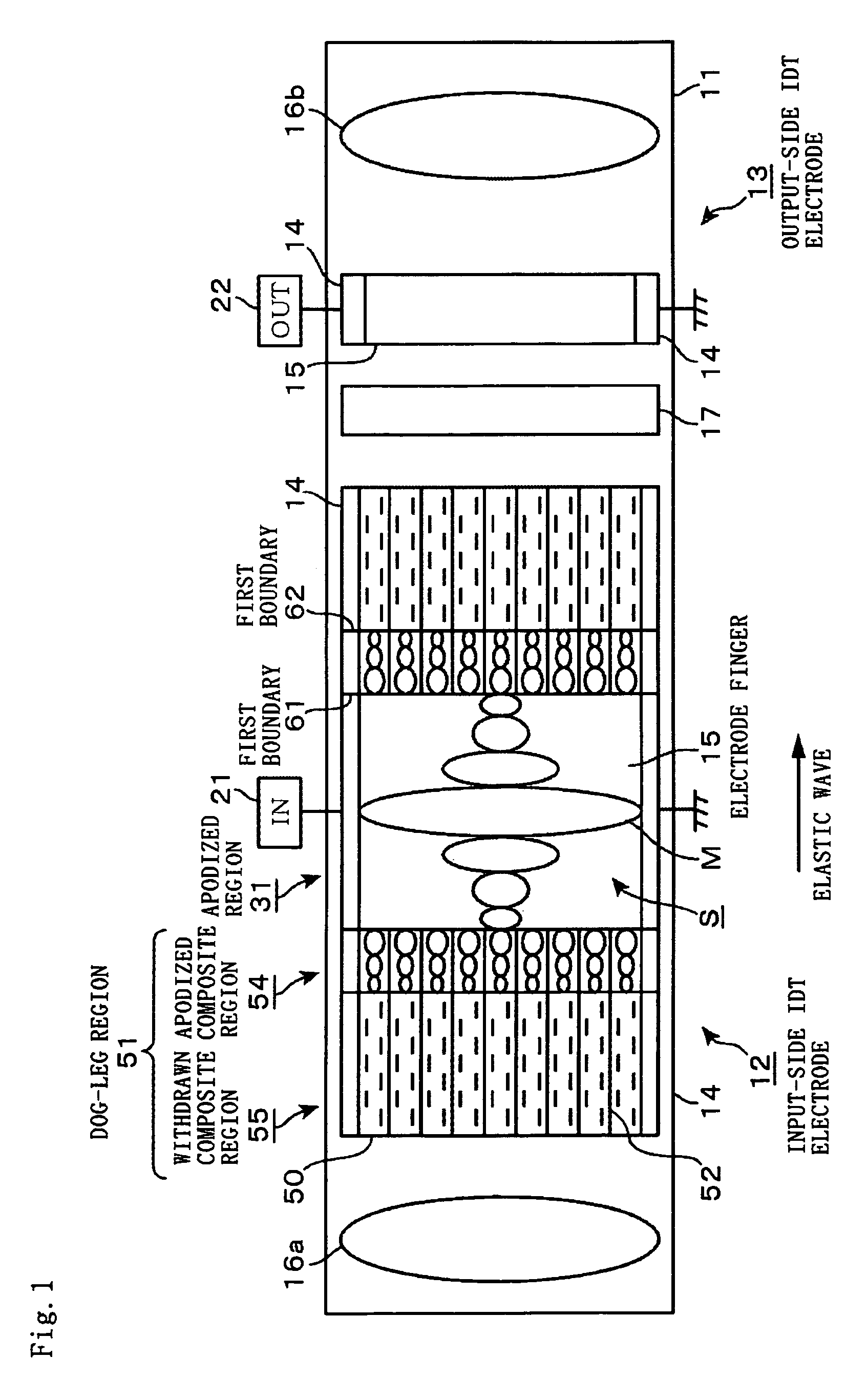
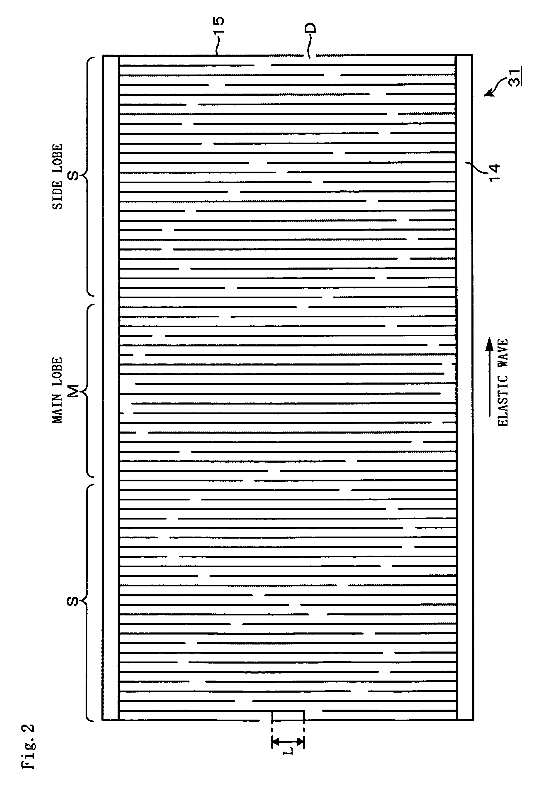
[0028]According to the transversal type filter of the present invention, in at least either of the input IDT and the output IDT formed on the piezoelectric substrate, the apodized region in which the weighting is performed on the aperture of the finger electrodes using the apodizing method is formed on the region in which the weighting amount of the finger electrodes takes the maximum value in the electrode, and in at least either of the regions adjacent to the apodized region in the propagation direction of the elastic wave, the apodized composite region is formed by dividing the propagation region of the elastic wave into the plurality of propagation paths in parallel with the propagation direction of the elastic wave using the dog-leg method, in which in each of the propagation paths, the weighting is performed on the aperture of the finger electrodes using the apodizing method. Accordingly, the weighting of the finger electrodes can be finely and continuously performed in the apodized region, and it is possible to obtain a large aperture between each of the finger electrodes in the apodized composite region compared to a case in which the finger electrodes are weighted using only the apodizing method, so that it is possible to suppress the diffraction of the elastic wave output from the apodized composite region while finely and continuously performing the weighting on the finger electrodes. Therefore, as a whole filter, it is possible to accurately design the filter so that an output signal has an intended intensity, and further, it is possible to suppress energies of the elastic waves lost by the diffraction to a low level, resulting that the flatness of the signal level in the frequency pass band can be increased, and further, the selectivity of signal (attenuation characteristic) can be enhanced.
[0029]In addition, on the region in the apodized composite region on the opposite side of the apodized region, the withdrawn region in which the crossing position of the finger electrodes is withdrawn by the withdrawal method is formed, so that it is possible to obtain the long aperture of the finger electrodes, and the diffraction of the elastic wave can be suppressed. Further, it is possible to reduce the weighting amount while obtaining the long aperture between each of the finger electrodes by increasing the number of divisions of the propagation paths in the aforementioned apodized composite region and by withdrawing the crossing position of the finger electrodes in the withdrawn region, for example, so that by increasing the number of finger electrodes, it is possible to form a large number of crossing regions between the finger electrodes in which the elastic wave is excited or received. Therefore, it is possible not only to suppress the diffraction of the elastic wave but also to widen the frequency pass band of the filter.

Problems solved by technology

Further, if the elastic wave is propagated to, for example, a region deviated in the longitudinal direction from the region between the bus bars 104, 104 of the output IDT 103 due to the diffraction, the elastic wave that is not received is generated, which results in loss of energy.
However, since the withdrawal method performs the weighting depending on the presence / absence of the finger electrodes 105, the weighting cannot be conducted continuously as in the apodizing method and the weighting amount becomes discrete, so that it lacks an expression of characteristic.
Accordingly, the application of only this method is not suitable for realizing the widening of the frequency pass band, the improvement of flatness of the signal level or the improvement of attenuation characteristic (enhancement of the selectivity) in the frequency pass band.
The weighting methods described above have advantages and disadvantages as shown in FIG. 22, and each method is inadequate to satisfy the aforementioned standard.
Patent Documents 1 to 6 disclose the weighting method such as the dog-leg method, but, no studies have been done regarding the above-described problems.

Method used


Image

  • Transversal type filter
  • Transversal type filter
  • Transversal type filter

Examples


Embodiment Construction

)

[0052]A transversal type filter being an embodiment of the present invention will be described with reference to FIG. 1 to FIG. 6. The transversal type filter is provided with an input (transmitting side) IDT 12 and an output (receiving side) IDT 13 formed on a surface of a piezoelectric substrate 11 by being separated from each other in a longitudinal direction of the piezoelectric substrate 11. Between these input IDT 12 and output IDT 13, a shield electrode 17 for suppressing coupling between the input IDT 12 and the output IDT 13 is formed. The shield electrode 17 is formed as, for instance, a film over which a metal is formed, a grating electrode provided with a large number of finger electrodes extending in a direction orthogonal to a propagation direction of an elastic wave and a pair of bus bars for connecting both ends of the finger electrodes, or the like. On lateral positions of the input IDT 12 and the output IDT 13 on both end sides of the piezoelectric substrate 11 in...


PUM


Abstract

To provide a transversal type filter having weighted finger electrodes of at least either of an input IDT and an output IDT provided on a piezoelectric substrate, in which a diffraction of elastic wave output from an end face of the weighted IDT electrode is suppressed, a band width is wide, and a high flatness and a high selectivity are realized. In at least either of an input IDT and an output IDT, an apodized region in which a weighting is performed by using an apodizing method with which an aperture of finger electrodes is continuously changed is formed on a center portion of the electrode with respect to a propagation direction of an elastic wave, and dog-leg regions in which a weighting is performed by using a dog-leg method with which the aperture is made into 1 / n by floating electrodes to form n tracks are formed on both sides of the apodized region. Subsequently, finger electrodes in each track of the dog-leg region are further weighted by using the apodizing method.

Description

BACKGROUND OF THE INVENTION[0001]1. Field of the Invention[0002]The present invention relates to a transversal type filter utilizing an elastic wave such as a SAW (Surface Acoustic Wave).[0003]2. Description of the Related Art[0004]A SAW device utilizes surface acoustic waves, and by arranging electrodes called an IDT (inter-digital transducer) on a piezoelectric substrate to perform an electromechanical interconversion between an electrical signal and an elastic wave, it provides frequency selection (band filter) characteristics. A SAW filter, which is one of such SAW devices, is used as a band-pass filter for various communication devices such as, for instance, a television broadcast transmitting station. In recent years, according to the decision of a shift from analog broadcasting to digital broadcasting in the year 2011, the band-pass filter for the digital broadcast transmitting station has been required to have a wide frequency pass band, as its characteristic. Further, this ...

Claims


Application Information

Patent Timeline
Patent Type & Authority Patents(United States)
IPC IPC(8): H03H9/145H03H9/64
CPCH03H9/02748H03H9/02795H03H9/1452H03H9/14526H03H9/1455
Inventor TSUDA, TADAAKI
Owner NIHON DEMPA KOGYO CO LTD
Learn More