
High-resolution surface testing method

A surface testing, high-resolution technology, used in measuring devices, analyzing materials, and using wave/particle radiation for material analysis. , sharp focus beam spot, optimize the effect of focusing effect

Active Publication Date: 2018-12-18
JINHUA VOCATIONAL TECH COLLEGE
View PDF7 Cites 0 Cited by
  • Summary
  • Abstract
  • Description
  • Claims
  • Application Information

AI Technical Summary

Problems solved by technology

[0003] The defect of the existing technology is that in a working mode of the atomic beam microscope, the Fresnel zone plate is used to focus the atoms in the form of de Broglie matter waves, and the ultimate resolution is determined by the outermost part of the Fresnel zone. Due to the low energy of the atomic beam, the atoms will not penetrate solid materials, so the ring used to transmit atoms on the Fresnel zone plate must adopt an unsupported structure, which is relatively complex in processing. It is very difficult, and the focusing effect of the atomic beam is not good enough, and the beam spot will be interfered by high-order diffraction. The high-resolution surface testing method can solve the problem

Method used


Image

  • High-resolution surface testing method
  • High-resolution surface testing method
  • High-resolution surface testing method

Examples


Embodiment Construction

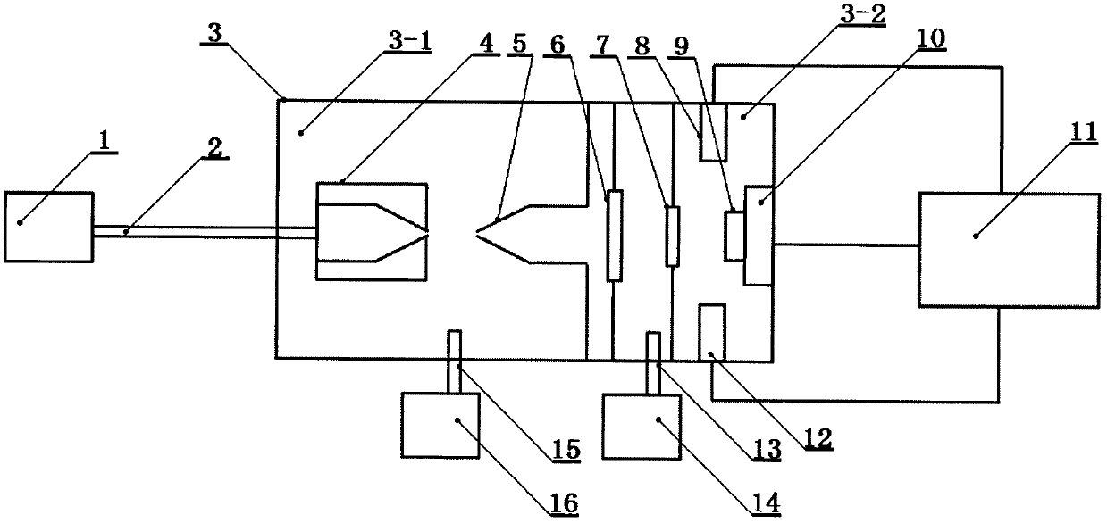
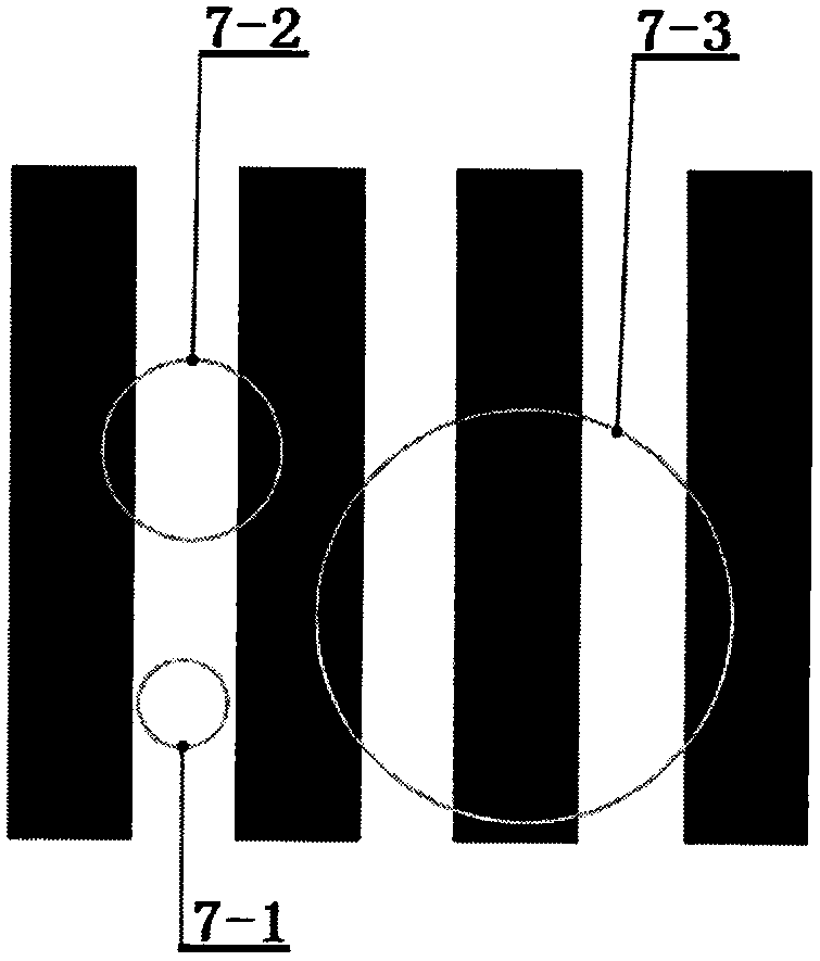
[0027] Such as figure 1 It is a schematic diagram of the high-resolution surface testing device of the present invention. The high-resolution surface testing device mainly includes a gas storage tank (1), a gas pipe (2), and is connected by a cavity I (3-1) and a cavity II (3-2). Vacuum cavity (3), injection head (4), flow divider (5), gas transmission window (6), atomic diffraction sheet (7), atomic diffraction sheet through hole type I (7-1), atomic Diffraction sheet through-hole type II (7-2), atomic diffraction sheet through-hole type III (7-3), detector I (8), sample (9), sample stage (10), computer (11), detector II(12), suction port I(13), vacuum pump group I(14), gas suction port II(15), vacuum pump group II(16), the cavity I(3-1) and cavity II(3- 2) Connected through the flow divider (5), the cavity II (3-2) is connected to the vacuum pump group I (14) through the suction port I (13), and the cavity I (3-1) is connected to the vacuum pump through the suction port II (1...


PUM


Abstract

The invention relates to the technical field of microscopy of materials. A high-resolution surface testing method comprises the following steps that a vacuum pump set is started to vacuumize a cavity,so that the vacuum in the cavity I is better than 1 / 10 Pa, and the vacuum in the cavity II is better than 1 / 100 Pa; a gas storage tank outputs gas to an injection head, gas atoms enter the cavity I in a free jet mode, and the gas atoms pass through a splitter and enter the cavity II in an atomic beam flow mode; the atomic beam flow sequentially passes through a gas transmission window sheet and an atomic diffraction sheet and then is emitted to the surface of a sample; a sample stage is horizontally moved in the range of 2*2 microns, so that the surface of the sample can be directly irradiated by an atomic beam; a detector I has higher detection efficiency of atoms with small atomic weight, and a detector II has higher detection efficiency of atoms with large atomic weight; when the gas in the gas storage tank is helium gas, the detector I is started; when the gas in the gas storage tank is neon gas or argon gas or krypton gas, the detector II is started; part of atoms reflected by the surface of the sample enter the detector, and the obtained data is input into a computer; and relevant information of the surface of the sample is obtained.

Description

technical field [0001] The invention relates to the field of microscopic technology for materials, in particular to a high-resolution surface testing method which uses atomic beams to scan the surface of a sample and has a specially designed atomic diffraction sheet. Background technique [0002] In the field of microscopic technology, the existing electron microscope can only image conductive samples, and the electron beam emitted by the electron microscope is of high energy, which will cause some sensitive sample surfaces to be damaged by radiation. The atomic beam microscope can overcome the above defects and image fragile or insulating samples. It usually uses inert gas atoms as the emitting atoms. The energy of the atomic beam of the inert gas is very low and its chemical properties are very stable. Obtain an image of the surface of the sample. The working principle of the atomic beam microscope is: in a high vacuum, the free atomic flow passes through the nozzle and t...

Claims


Application Information

Patent Timeline
Patent Type & Authority Applications(China)
IPC IPC(8): G01N23/20008G01N23/207
CPCG01N23/20008G01N23/207G01N2223/105G01N2223/05
Inventor 张向平赵永建
Owner JINHUA VOCATIONAL TECH COLLEGE
Learn More