Communication apparatus

a technology of communication apparatus and communication channel, which is applied in the field of communication channel, can solve the problems of user degraded signal, unit price of frequency spectrum raised,

Inactive Publication Date: 2012-02-28
FUJITSU LTD
View PDF13 Cites 29 Cited by
  • Summary
  • Abstract
  • Description
  • Claims
  • Application Information

AI Technical Summary

Benefits of technology

[0018]The present communication apparatus aims at providing a communication apparatus capable of controlling the transmission power from a base station in fractional frequency reuse (FFR).

Problems solved by technology

Recently, high-speed wireless communications have been developed, and the unit price of a frequency spectrum has been raised as the frequency spectrum has been a resource limited to be efficiently used.
However, the reuse method indicates the possibility that a user of a cell edge receives a degraded signal by the interference from an adjacent cell.

Method used


Image

  • Communication apparatus
  • Communication apparatus
  • Communication apparatus

Examples


Embodiment Construction

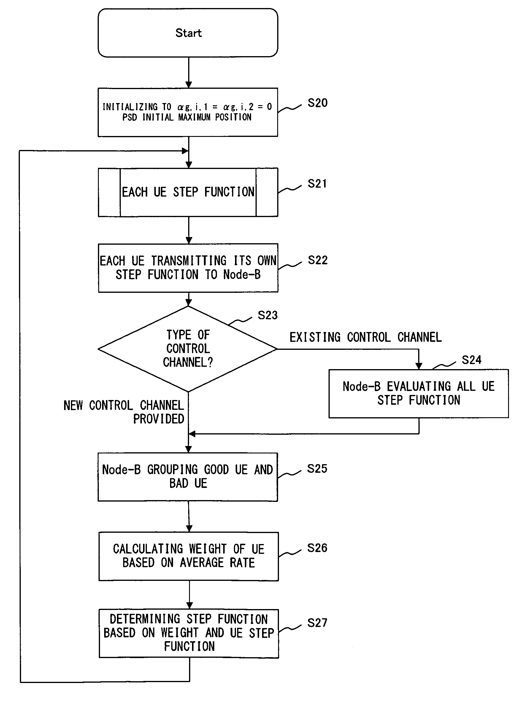
[0033]In the present embodiment, the downlink power control (to be more correct, power spectrum density (PSD)) from a base station is realized based on a step function. In this scheme, the distribution of the downlink (DL) transmission PSD over the entire band is adjusted by controlling the slope or a segment of the step function based on the interference level autonomously learned from the adjacent cell. Furthermore, a scheduler functions of assigning user equipment (UE) of a cell edge in a subcarrier in which large transmission PSD is distributed. On the other hand, to the UE at the center of the cell, a subcarrier in which small transmission PSD is distributed is assigned. The advantages of the scheme are:

[0034]when the number of steps is 3, the invention covers most FFR schemes;

[0035]as in the interference control method using other types of FFR, a large user coverage gain can be obtained in this method; and

[0036]it is not necessary to assign a control channel, and the FFR opera...


PUM


Abstract

Node-B transmits a power profile of each frequency of transmission data as a step function to a UE. Each UE measures the amount of interference of a received signal, evaluates SINR over the entire frequency band with the power of the received signal, and transmits the evaluation result to Node-B. Node-B evaluates the interference profile in Node-B from the information about the SINR transmitted from the UE and the power of the transmission signal, and determines the frequency profile of the power of the signal transmitted to the UE.

Description

BACKGROUND OF THE INVENTION[0001]1. Field of the Invention[0002]The present invention relates to a communication apparatus having an FFR (fractional frequency reuse) control mechanism using a step function.[0003]2. Description of the Related Art[0004]Recently, high-speed wireless communications have been developed, and the unit price of a frequency spectrum has been raised as the frequency spectrum has been a resource limited to be efficiently used. In the standard of 1xEV-DO, IEEE802.16E, LTE etc., frequency reuse has been a problem to be considered.[0005]FIGS. 1A through 1D are explanatory views showing various aspects of frequency reuse.[0006]The frequency reuse shown in FIG. 1A has a reuse factor of 1 indicating the sectors of all cells having the same frequency F, and high throughput can be attained when all sectors in a cell operate at the same frequency band. However, the reuse method indicates the possibility that a user of a cell edge receives a degraded signal by the inter...

Claims


Application Information

Patent Timeline
Patent Type & Authority Patents(United States)
IPC IPC(8): H04B7/00
CPCH04W16/10H04W52/243H04W52/143H04W16/12H04W52/38H04W52/241H04L5/0023
Inventor WU, JIANMINGAZUMA, MITSUHIROTANIGUCHI, TOMOHIKOFUKUDA, EISUKE
Owner FUJITSU LTD
Why Eureka
Try Eureka