Working fluid cooling control system for construction machine

a technology of working fluid and control system, which is applied in the direction of fluid couplings, servomotors, couplings, etc., can solve the problems of increasing the temperature of the hydraulic system, adversely affecting losing heat balance, so as to improve the life of the hydraulic device, improve the cooling performance, and reduce the failure of the hydraulic devi

Active Publication Date: 2012-03-06
NIHON KENKI CO LTD
View PDF13 Cites 1 Cited by
  • Summary
  • Abstract
  • Description
  • Claims
  • Application Information

AI Technical Summary

Benefits of technology

[0032]According to the present invention it is possible to improve the cooling performance before a rise in temperature of the working fluid, thereby prevent the occurrence of a temperature rise of the working fluid, diminish failures of hydraulic devices, and improve the machine lives thereof. Moreover, since the cooling performance is improved by increasing the minimum capacity of a hydraulic pump(s) to increase an average flow rate of the working fluid passing through the heat exchanger, a worsening of noise does not occur and it is possible to minimize a worsening of fuel efficiency.

Problems solved by technology

In this case, in the states of operations performed under severer conditions than in standard operations, such as, for example, a continuous high-load operation, an operation performed in a place of a very high ambient temperature such as in a tunnel, or an operation performed with the construction machine deteriorated, the heat balance is lost, which increases the temperature of the hydraulic system and adversely affects the machine lives of hydraulic devices.
However, if the specifications of the cooling system are optimized beforehand so as to ensure a heat balance under severer conditions than in standard operations such as, for example, a continuous high-load operation, not only the problem of overengineering occurs relative to the standard operations most frequent in general use, but also it is uneconomical.
If the capacity of the heat exchanger is increased as a countermeasure, the entire cooling system becomes larger in size, leading to an increase of cost and an increase in size of the construction machine concerned, or the problem may arise that the noise level becomes higher because the cooling air volume needs to be increased.

Method used


Image

  • Working fluid cooling control system for construction machine
  • Working fluid cooling control system for construction machine
  • Working fluid cooling control system for construction machine

Examples


Embodiment Construction

[0077]An embodiment of the present invention will be described hereinunder with reference to the drawings.

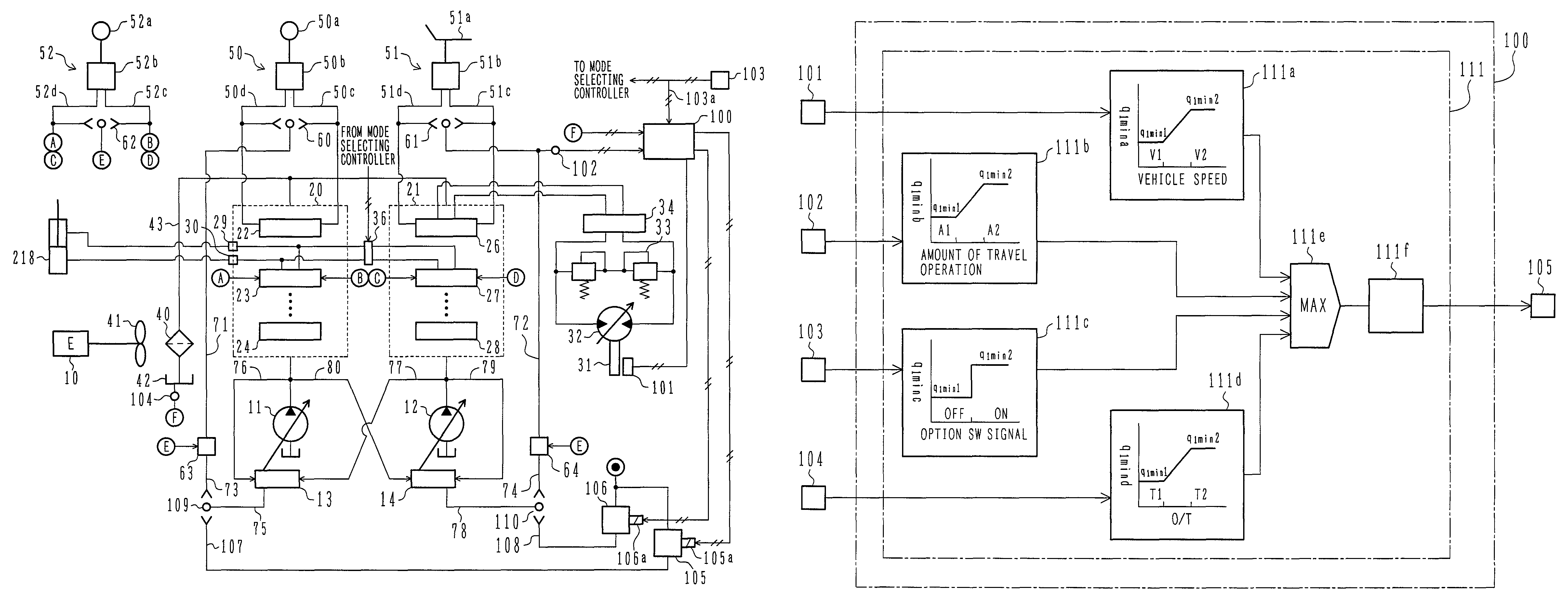
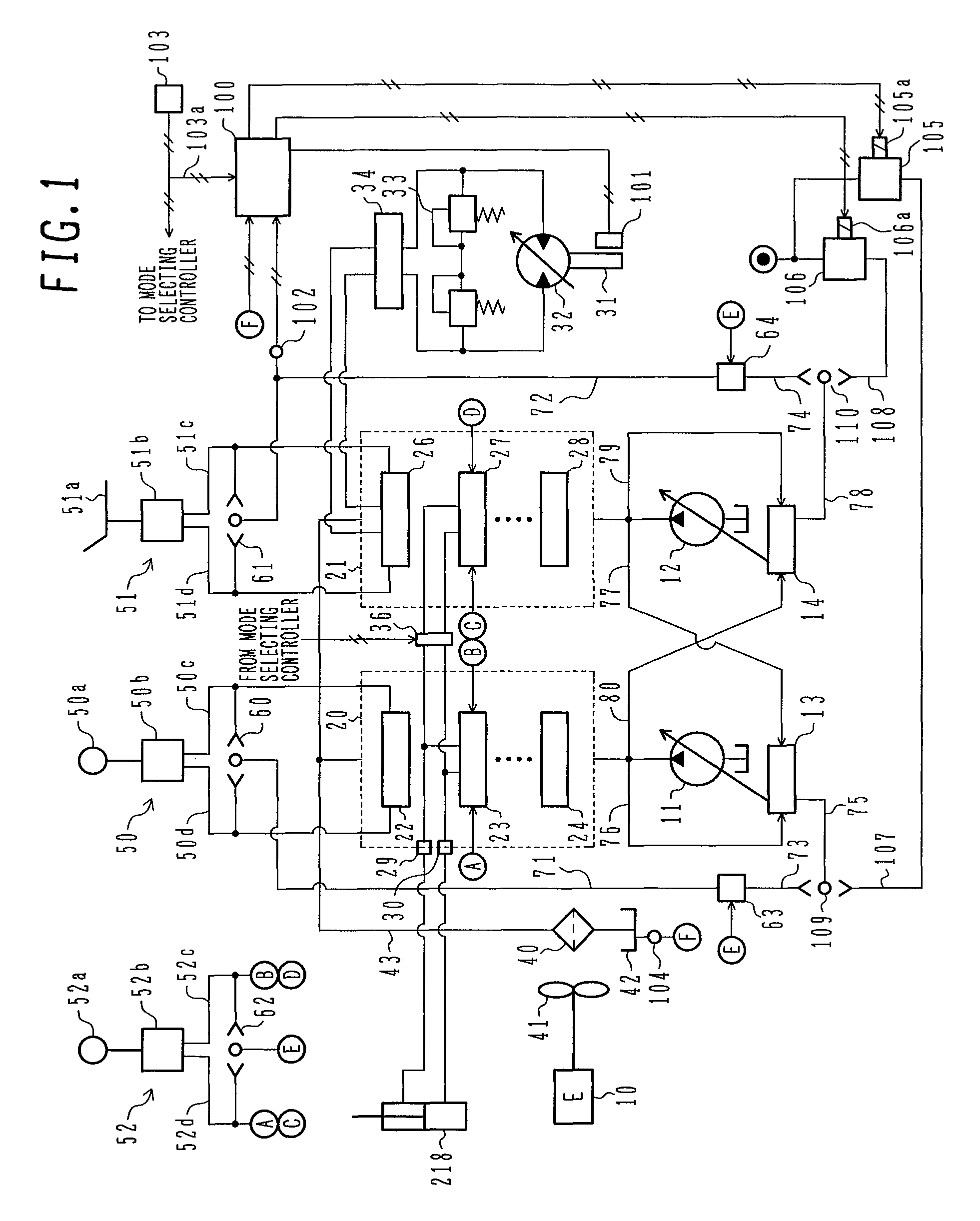
[0078]FIG. 1 illustrates a working fluid cooling control system for a construction machine according to an embodiment of the present invention, together with a hydraulic drive system (hydraulic system).

[0079]In FIG. 1, the hydraulic drive system includes two variable displacement type hydraulic pumps 11 and 12 and two control valve groups 20 and 21. The hydraulic pumps 11 and 12 are provided with tilt control mechanisms 13 and 14, respectively, for controlling respective tilting angles.

[0080]The control valve group 20 is made up of plural control valves including center bypass type control valves 22, 23 and 24 and is connected to the hydraulic pump 11. The control valve group 21 is made up of plural control valves including center bypass type control valves 26, 27 and 28 and is connected to the hydraulic pump 12. The control valves, which are connected to various hydraulic actua...


PUM


Abstract

A working fluid cooling control system has a controller 100 that receives inputs signals from a traveling motor speed pickup 101, a pressure sensor 102, a signal receiving line 103a of an option selecting switch 103 and a temperature sensor 104. The controller performs predetermined arithmetic processing and controls proportional solenoid valves 105 and 106. The pressures controlled by the solenoid valves are compared with positive control command pressures in shuttle valves 109 and 110. In this way, in the case of an operation pattern corresponding to a rise in temperature of the working fluid, minimum tilting angles of hydraulic pumps 11 and 12 are increased to increase an average flow rate of the working fluid passing through an oil cooler 40, thereby increasing an average heat discharge amount and reducing an equilibrium temperature of the working fluid.

Description

TECHNICAL FIELD[0001]The present invention relates to a working fluid cooling control system for a construction machine comprising a variable displacement type hydraulic pump, plural members to be operated by the hydraulic pump, and a heat exchanger for cooling working fluid (working oil) as an operating medium.BACKGROUND ART[0002]In a conventional construction machine, especially a conventional hydraulic excavator or the like, the specifications of a cooling system including a heat exchanger as a cooler for working fluid are optimized so as to ensure a heat balance of a prime mover, a hydraulic system, etc. on the basis of standard operations using a bucket. In this case, in the states of operations performed under severer conditions than in standard operations, such as, for example, a continuous high-load operation, an operation performed in a place of a very high ambient temperature such as in a tunnel, or an operation performed with the construction machine deteriorated, the hea...

Claims


Application Information

Patent Timeline
Patent Type & Authority Patents(United States)
IPC IPC(8): F16D31/02E02F9/00E02F9/22F15B11/00F15B21/0423
CPCE02F9/226E02F9/2292E02F9/2296F15B21/042F15B2211/20546F15B2211/20576F15B2211/30595F15B2211/62F15B2211/6336F15B2211/6343F15B2211/6346F15B2211/6652F15B2211/6658F15B2211/7135F15B2211/85F15B21/0423F15B21/04F15B11/00E02F9/22
Inventor SATAKE, HIDETOSHI
Owner NIHON KENKI CO LTD
Why Eureka
Try Eureka