Unlock instant, AI-driven research and patent intelligence for your innovation.

Angular velocity sensing element

a technology of angular velocity and sensing element, which is applied in the direction of acceleration measurement using interia force, turn-sensitive devices, instruments, etc., can solve the problems of excessively large amplitude of oscillation arms with respect to fixing ends, so as to suppress the excessive oscillation of oscillation arms, and prevent the oscillation arms from being damaged or broken

Active Publication Date: 2012-03-06
TDK CORPARATION
View PDF5 Cites 1 Cited by
  • Summary
  • Abstract
  • Description
  • Claims
  • Application Information

AI Technical Summary

Benefits of technology

The present invention provides an angular velocity sensing element with an oscillation arm and a stopper member that limits the oscillation range of the arm. This prevents damage or breakage to the oscillation arm in case of an excessive shock. The stopper member can be arranged along the same plane as the oscillation arm or in a different plane to limit out-of-plane oscillation. The stopper member has a part that comes in touch with the oscillation arm, which disperses the impulsive force and protects the oscillation arm from damage. The invention helps to prevent excessive oscillation of the oscillation arm and enhances the productivity and reliability of the angular velocity sensing element.

Problems solved by technology

For example, a free end side (open end side) of the oscillation arm may be oscillated at excessively large amplitude with respect to a fixing end, or portions between a plurality of fixing ends of the oscillation arm may be oscillated at excessively large amplitude with respect to the fixing ends.

Method used


Image

  • Angular velocity sensing element
  • Angular velocity sensing element
  • Angular velocity sensing element

Examples


first embodiment

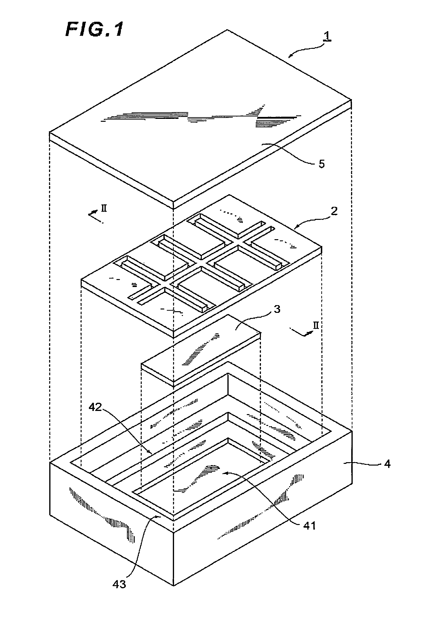
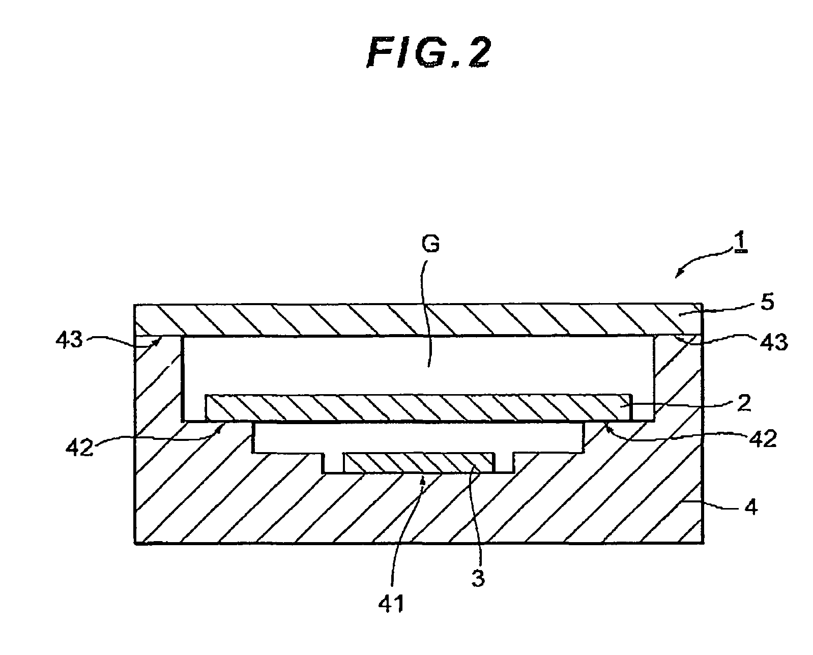
[0034]FIG. 1 is an exploded perspective view of an inner configuration of an angular velocity sensor device 1 according to a first embodiment. FIG. 2 is a cross-sectional view taken along II-II line in the angular velocity sensor device 1.

[0035]In the angular velocity sensor device 1, an upper cover member 5 is disposed on top of a case 4 to form an inner space G (see FIG. 2) in which an angular velocity sensing element 2 and an integrated circuit element 3 are arranged.

[0036]As will be described later, the angular velocity sensing element 2 is configured to transmit drive signals to piezoelectric elements provided at drive arms of the angular velocity sensing element 2, and to receive detection signals outputted from piezoelectric elements provided at sensor arms of the angular velocity sensing element 2. The case 4 is formed by stacking a plurality of thin ceramic plates, for example, and has a stepped recess that can accommodate the angular velocity sensing element 2 and the inte...

second embodiment

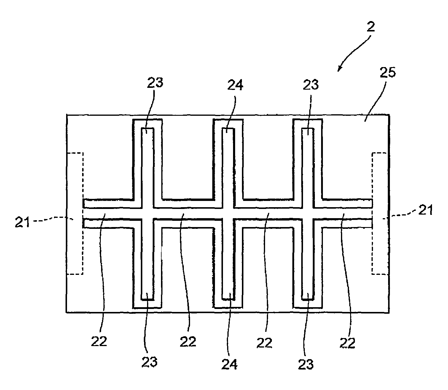
[0064]The angular velocity sensing element 2 according to a second embodiment is the same with that of the first embodiment except the shape of the first stopper member 25 in a touch portion thereof, which comes in touch with each of the oscillation arms. FIG. 11A is a plan view illustrating a principal part of the first stopper member 25. FIG. 11B is a plan view illustrating a state where the drive arm 23 or the sensor arm 24 is in touch with the first stopper member 25.

[0065]As shown in FIG. 11A, in the present embodiment, the first stopper member 25 in a touch portion “S” is processed into a form for matching the form of the drive arm 23 or the sensor arm 24 in touch with the first stopper member 25. The form of the first stopper member 25 may be processed so as to match the form of the transmission arm 22.

[0066]According to the present embodiment, the portion of each oscillation arm, which comes in touch with the first stopper member 25 is supported by a face of the first stoppe...

third embodiment

[0067]In the angular velocity sensing element 2 described in a third embodiment, the oscillation range of the oscillation arms is also limited in the direction perpendicular to the plane in which the oscillation arms are formed.

[0068]FIG. 12 is a cross-sectional view illustrating the angular velocity sensing element 2 according to the third embodiment.

[0069]As shown in FIG. 12, two second stopper members 26 and 26 are arranged in the direction perpendicular to the plane where the oscillation arms consisting of the transmission arm 22, the drive arms 23 and the sensor arms 24 are formed. The second stopper members 26 and 26 each has a shape of a plate and are fixed to the fixing portion 21 and an outer edge of the first stopper member 25 via an adhesion layer 27, for example. Unlike the first stopper member 25, each second stopper member 26 is not required to be formed of the same material as the oscillation arms. Thus, glass, for example, may be used as the material.

[0070]In this wa...


PUM


Abstract

An angular velocity sensing element is provided, which is able to prevent breakage of an oscillation arm even when an excessively large shock is given. An angular velocity sensing element 2 according to the present embodiment includes oscillation arms 22, 23 and 24 formed of a semiconductor material, and a stopper member provided to limit the oscillation range of the oscillation arms. As such a stopper member, a first stopper member 25 is provided, for example, which limits the oscillation range of the oscillation arms at least within a single plane of the arms. Fixing portions 21, the oscillation arms 22, 23 and 24 and the first stopper member 25 are integrally formed by processing a semiconductor material, such as silicon.

Description

BACKGROUND OF THE INVENTION[0001]1. Field of the Invention[0002]The present invention relates to an angular velocity sensing element which detects angular velocity of an object.[0003]2. Description of the Related Art[0004]Angular velocity sensing elements have been utilized in the technology of autonomously controlling attitude such as of boats, airplanes and rockets. Recently, use of such angular velocity sensing elements has been extended to small electronic devices, such as car navigation systems, digital cameras, video cameras and cellular phones. With this trend, there has been a need for the angular velocity sensing elements to have smaller size and lower height (reduced thickness).[0005]Oscillation arms of oscillation type angular velocity sensors have prevalently been fabricated by machining and molding piezoelectric materials. However, since the accuracy of machining naturally has a limitation, it has been difficult to meet the need of the smaller size and lower height in t...

Claims


Application Information

Patent Timeline
Patent Type & Authority Patents(United States)
IPC IPC(8): G01C19/56G01C19/5621H01L41/08H01L41/187
CPCG01C19/5607
Inventor UNNO, KENNOGUCHI, TAKAOTOCHI, KENICHIMAEKAWA, KAZUYA
Owner TDK CORPARATION