Metal-sealing material-feedthrough and utilization of the metal-sealing material feedthrough with an airbag, a belt tensioning device, and an ignition device

a technology of metal-sealing material and feedthrough, which is applied in the direction of ammunition fuzes, electric fuzes, weapons, etc., can solve the problems of uneconomic fabrication, material intensive and expensive construction types, and the limit of punching fabrication, so as to achieve excellent welding, high mechanical rigidity, and high corrosion resistance

Active Publication Date: 2012-03-06
SCHOTT AG
View PDF41 Cites 11 Cited by
  • Summary
  • Abstract
  • Description
  • Claims
  • Application Information

AI Technical Summary

Benefits of technology

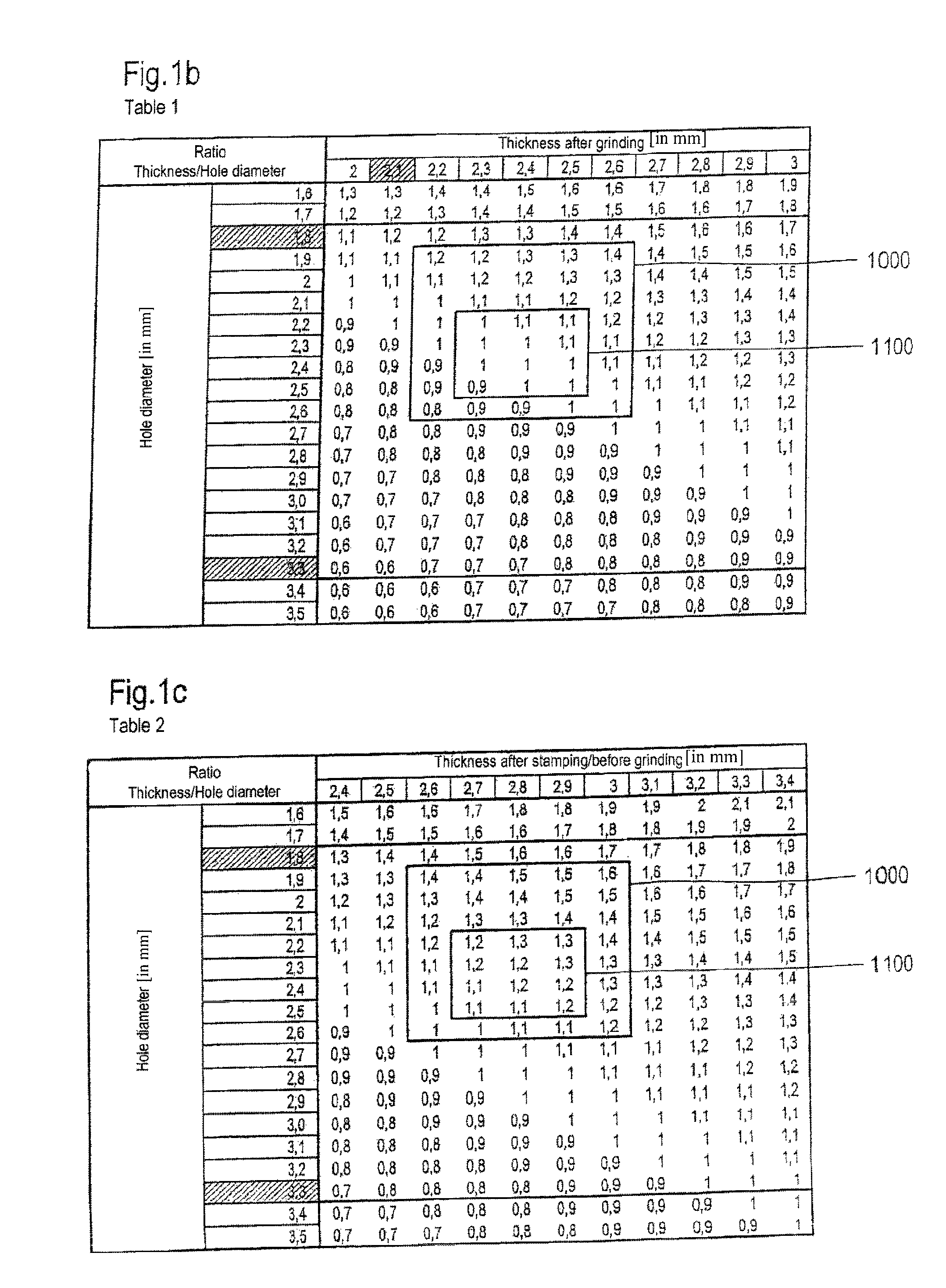
[0017]For applications in ignition devices for airbags base bodies having a thickness of between 1 mm and 5 mm, preferably 1.5 mm and 3.5 mm, especially preferably 1.8 mm to 3.0 mm, more especially preferably 2.0 mm to 2.6 mm are used. Even with consistently sized metal pins this represents a considerable saving in materials due to the smaller dimensions compared to the pivoted component which has thicknesses for example, of 3.2 mm to 5 mm, as well as providing an energy saving manufacturing process. In addition, the reduction in the support surface for the sealing material slug which is inherent with the reduction in the thickness can be compensated for with regard to its function, by simple measures which require almost no additional expenditure.
[0022]The current invention provides for cost effective manufacturing processes and starting materials wherein the material usage is considerably reduced. The entire base body may also be constructed as an integral component into which the metal pin is fused by way of the sealing material, in other words for example by way of the glass slugs. An additional substantial advantage is that even under an increased load upon the glass slug—for example a pressure load—pushing the glass blob with the metal pin out of the feedthrough opening can probably be avoided. The entire embodiment when compared with a pivoted component is lower in height and assures a secure bonding of the glass slug in the base body, even during high ejection force.
[0024]In accordance with another embodiment the second metal pin is placed or secured as a grounding pin to ground at the back side of the base body. This eliminates additional measures of having to ground a metal pin that is sealed into the base body with sealing material, or having to connect it electrically with the base body. In addition, only one pin then needs to be sealed into one feedthrough opening, providing a plurality of possibilities to securely seal the single pin completely in circumferential direction; and the possible connection area for the ground pin can be enlarged.

Problems solved by technology

One fundamental problem in this embodiment is that this type of construction is material intensive and expensive.
There are no restrictions regarding the material choices for the base body so that, depending upon design, especially when constructed as a pivoted component, the already mentioned disadvantages also occur, which only intensify through the additional necessary inclusion of the required ways for the increase of the tensile force, extraction force, and / or ejection force.
However, fabrication by way of punching is subject to limits with a view to individual material related parameters exceeding of which would render the fabrication uneconomical and which would also have a negative effect upon the available ejection force.

Method used


Image

  • Metal-sealing material-feedthrough and utilization of the metal-sealing material feedthrough with an airbag, a belt tensioning device, and an ignition device
  • Metal-sealing material-feedthrough and utilization of the metal-sealing material feedthrough with an airbag, a belt tensioning device, and an ignition device
  • Metal-sealing material-feedthrough and utilization of the metal-sealing material feedthrough with an airbag, a belt tensioning device, and an ignition device

Examples


Embodiment Construction

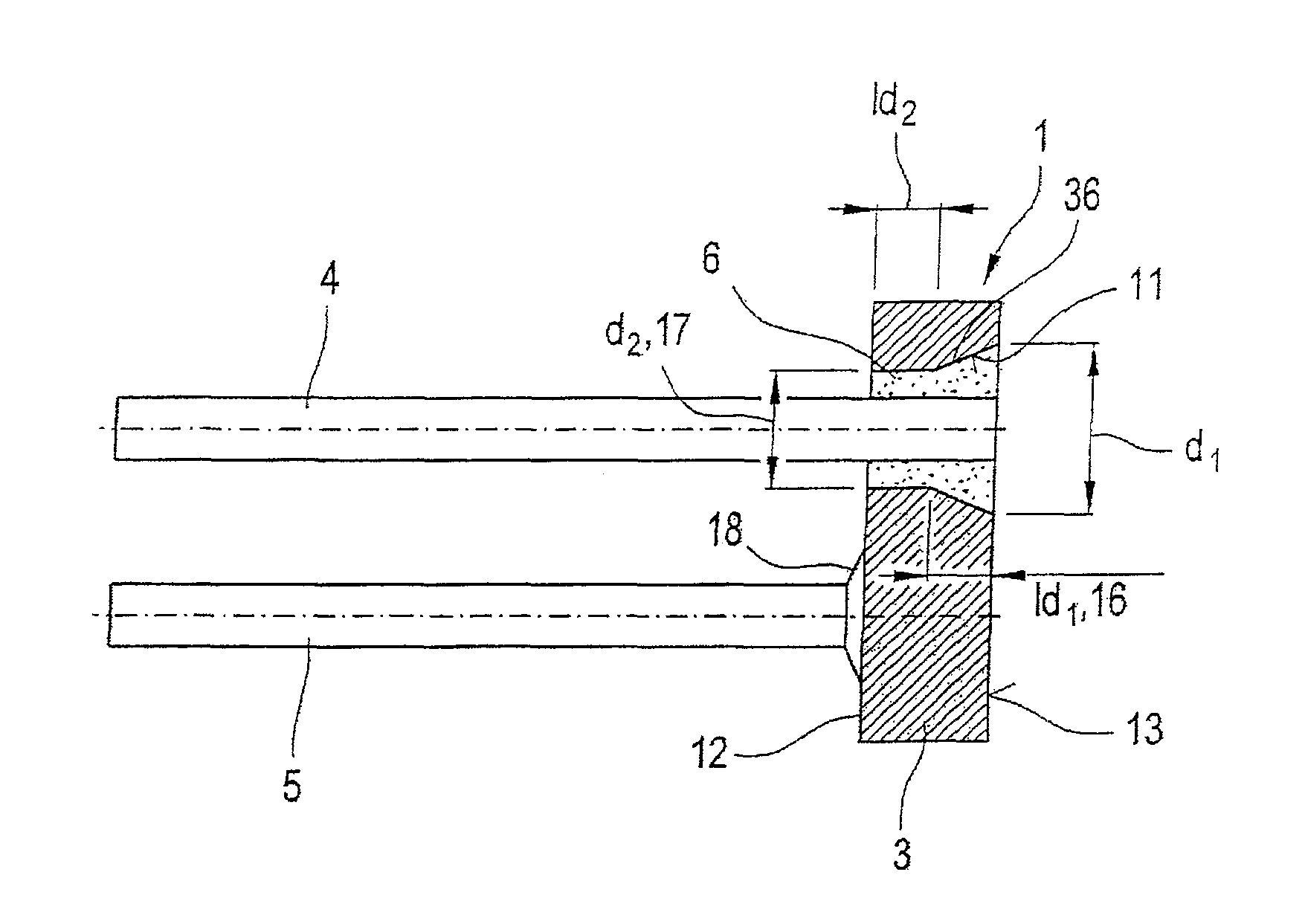
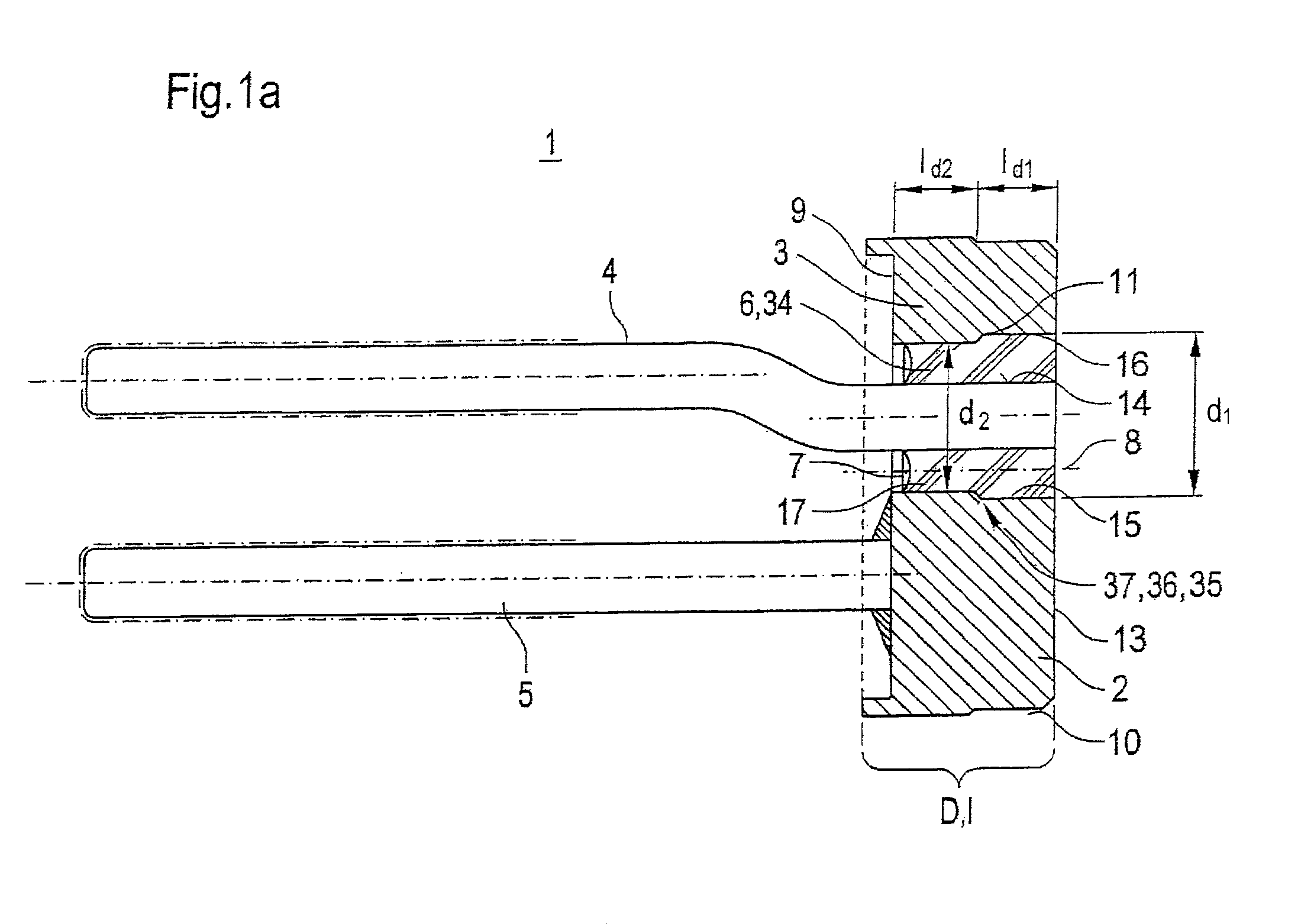
[0054]Referring now to the drawings, and more particularly to FIG. 1a, there is shown, with the assistance of an axial section, a first design of an inventively constructed metal-sealing material-feedthrough 1, which can be used as an igniter or an ignition device of an airbag. This includes a base body 3 forming a metal collar 2 with which two parallel metal pins 4 and 5 are electrically connected. The two metal pins 4 and 5 are located parallel to each other. One of said metal pins functions as a conductor while the second one is grounded. In the illustrated example the first metal pin 4 functions as conductor and the metal pin 5 as grounding pin. At least one of the metal pins, especially the one metal pin 4 functioning as conductor is inserted through the base body 3. In this context the metal pin 4 is sealed over a section of its length 1 in sealing material 34, especially in a glass slug 6 which is cooled from a molten glass mass. In the illustrated example the metal pin 4 pro...


PUM


Abstract

The present invention relates to a metal-sealing material-feedthrough for igniters of airbags or belt tensioning devices, especially glass-metal-feedthrough, including at least one metal pin which is located in a feedthrough opening in the base body in a sealing material, wherein the base body has a front side and a back side. Structure is provided between the front and the back side in order to avoid a relative movement of sealing material in the direction toward the back relative to the inside circumference of the feedthrough opening. At least the feedthrough opening is punched out of the base body. The base body is configured so that the ratio of thickness (D) of the base body to the maximum dimension of the feedthrough opening vertical to the axis direction of the feedthrough opening is in the range of between and including 0.9 to 1.6.

Description

BACKGROUND OF THE INVENTION[0001]1. Field of the Invention[0002]The current invention relates to a metal-sealing material-feedthrough. It further relates to usage as well as to a gas generator, airbag and belt tensioning device including an ignition device, comprehensively a metal-sealing material-feedthrough.[0003]2. Description of the Related Art[0004]Metal-sealing material feedthroughs are already known in various forms from the current state of the art. They are understood to be vacuum-tight seals of sealing materials, especially glass or synthetics to metal seals. In this type or arrangement the metals act as electrical conductors. We refer you to representative documentation U.S. Pat. No. 5,345,872, U.S. Pat. No. 3,274,937. Feedthroughs of this type are common in electronic and electrical engineering. The material used for sealing, especially glass, serves as an insulator. Typical metal-sealing material-feedthroughs are constructed such that metallic internal conductors are se...

Claims


Application Information

Patent Timeline
Patent Type & Authority Patents(United States)
IPC IPC(8): F42B3/12
CPCF42B3/103F42B3/198
Inventor FINK, THOMAS
Owner SCHOTT AG
Why Eureka
Try Eureka