Hydraulic damping device for drawer

a damping device and hydraulic technology, applied in the direction of vibration dampers, springs/dampers, springs, etc., can solve the problem of unsmooth movement of the piston rod, and achieve the effect of reducing noise, high damping resistance to the piston rod, and smoothening the return stroke of the piston rod

Active Publication Date: 2012-03-06
IP HLDG LLC
View PDF37 Cites 29 Cited by
  • Summary
  • Abstract
  • Description
  • Claims
  • Application Information

AI Technical Summary

Benefits of technology

[0003]The present invention has been accomplished under the circumstances in view. It is one object of the present invention to provide a hydraulic damping device for drawer, which imparts a high damping resistance to the piston rod as the piston rod is moved toward the inside of the cylinder, smoothening the return stroke of the piston rod. It is another object of the present invention to provide a hydraulic damping device for drawer, which allows the piston rod to be extended out of the cylinder at a high speed without much resistance and, which uses a shock absorber to absorb shocks and to buffer the impact when the piston rod is extended out of the cylinder, thereby lowering the noise level.
[0004]To achieve these and other objects of the present invention, the hydraulic damping device comprises a cylinder holding a hydraulic fluid, a piston rod moving in and out of the cyl...

Problems solved by technology

However, because the compression spring has a certain ...

Method used


Image

  • Hydraulic damping device for drawer
  • Hydraulic damping device for drawer
  • Hydraulic damping device for drawer

Examples


Embodiment Construction

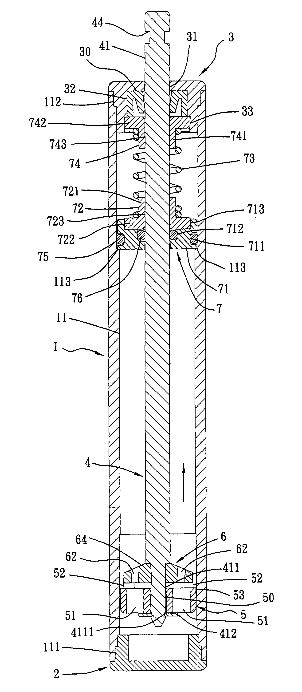
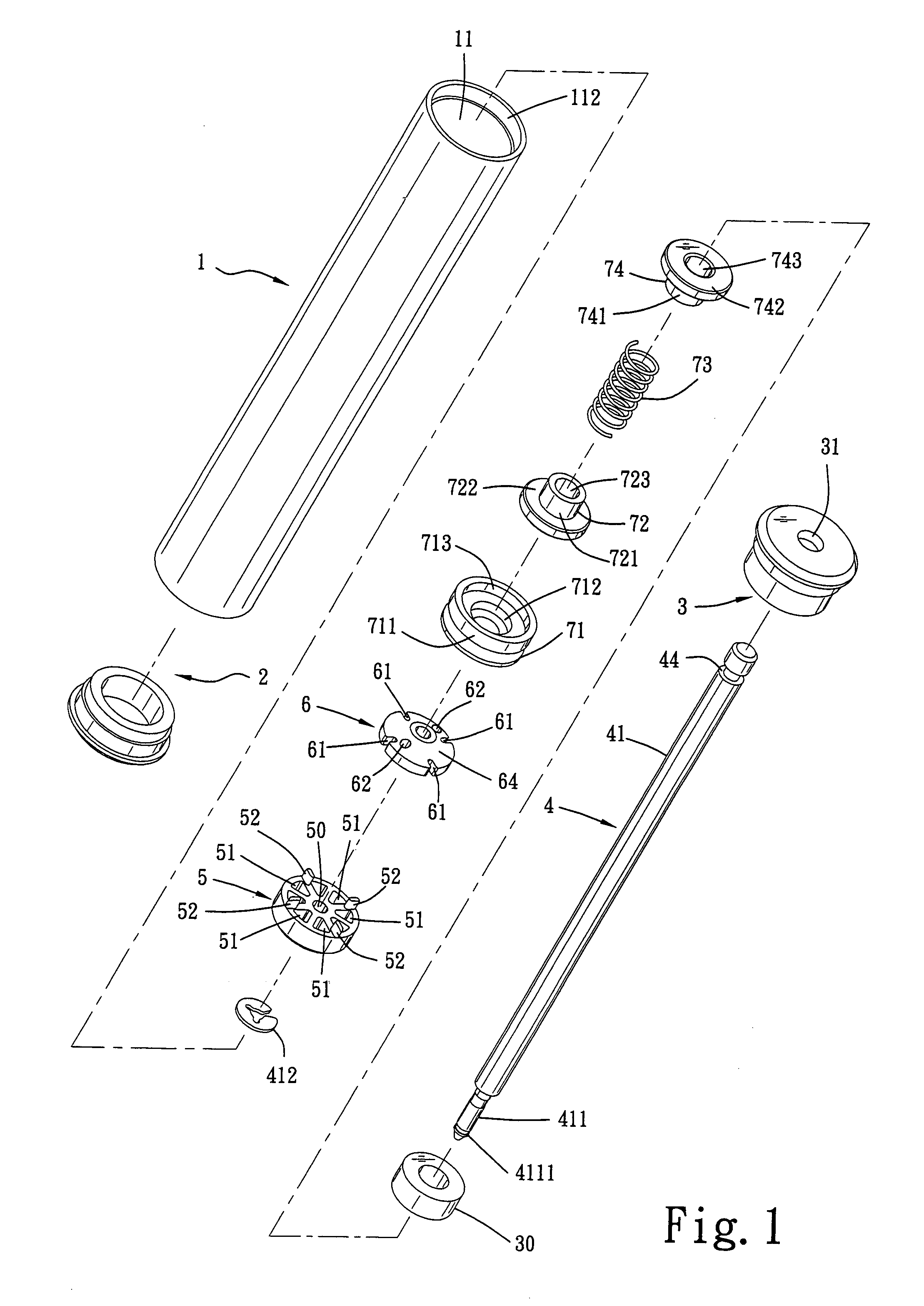
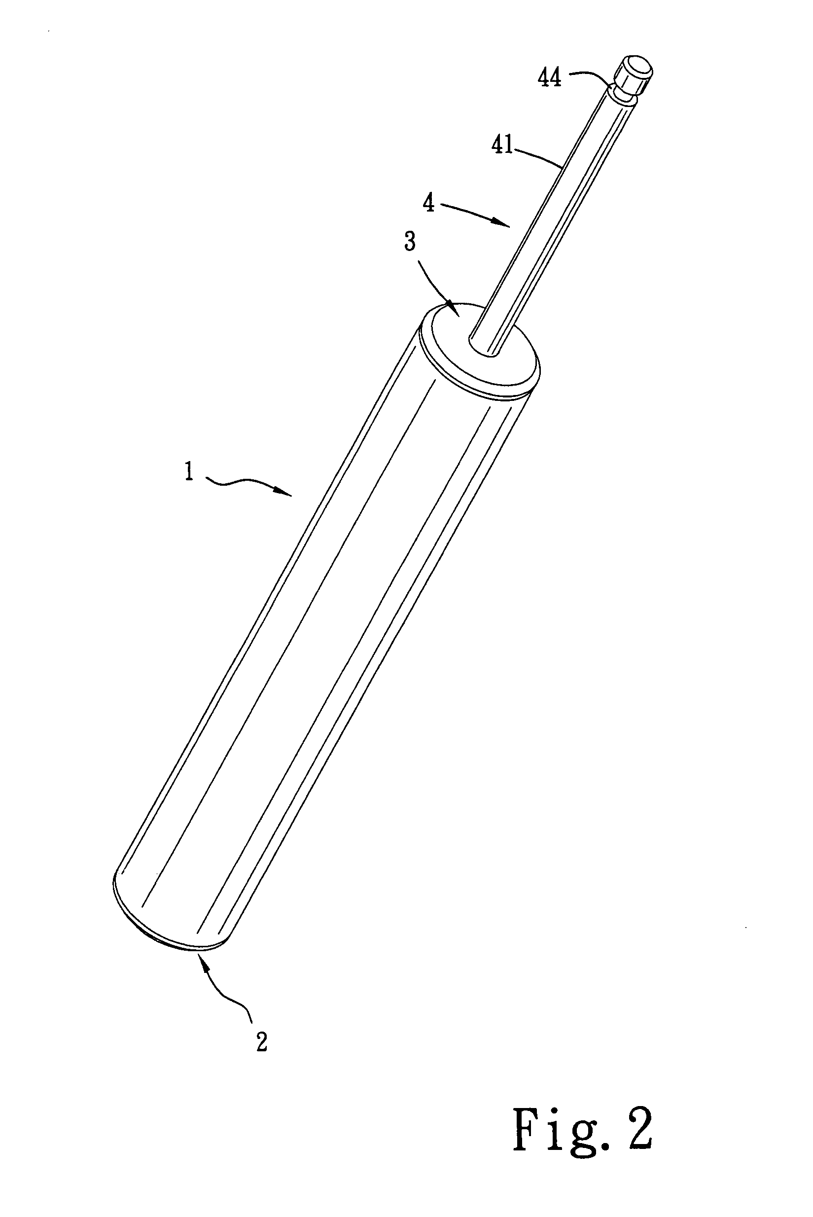
[0012]Referring to FIGS. 1-7, a hydraulic damping device for drawer in accordance with the present invention is shown comprised of a cylinder 1, a front cap 2, a rear cap 3, a piston rod 4, a piston 5, and a rigid valve block 6.

[0013]The cylinder 1 has a cylindrical peripheral wall 11 in which the piston 5 is moved with the piston rod 4 forwards / backwards, a front opening 111 defined in one end of the cylindrical peripheral wall 11 (see FIG. 7), and a rear opening 112 defined in the other end of the cylindrical peripheral wall 11.

[0014]The front cap 2 is sealed to the cylindrical peripheral wall 11 of the cylinder 1 by, for example, an ultrasonic sealing process to close the front opening 111 after filling of a hydraulic fluid in the cylinder 1 (see FIGS. 3 and 7).

[0015]The rear cap 3 is sealed to the rear opening 112 of the cylinder 1 by, for example, an ultrasonic sealing process to close the front opening 111, having a bottom accommodation chamber 32, an inside annular groove 33 ...


PUM


Abstract

A hydraulic damping device includes a cylinder holding a hydraulic fluid, a piston rod moving in and out of the cylinder and having a pin at one end inside the cylinder, a rigid valve block affixed to the inner end of the pin of the piston rod and having equiangularly spaced through holes, a retainer affixed to the outer end of the pin of the piston rod, a piston coupled to the pin of the piston rod and movable along the pin between the rigid valve block and the retainer and having a plurality of axially extending through holes, a number of the through holes of the piston being respectively aimed at the through holes of the rigid valve block for allowing the hydraulic fluid to pass through the piston in one direction at a high speed during outward stroke of the piston rod and to pass through the piston in the other direction at a low speed during inward stroke of the piston, and a shock absorber that buffers the impact of the rigid valve block when the piston rod is extended out of the cylinder.

Description

BACKGROUND AND SUMMARY OF THE INVENTION[0001]The present invention relates to damping devices and more particularly, to a hydraulic damping device for drawer, which buffers the reciprocating motion of the piston rod, allowing the piston rod to be moved out of the cylinder rapidly without much resistance and received into the inside of the cylinder slowly with much resistance. A shock absorber is provided to buffer the impact when the piston rod is extended out of the cylinder.[0002]U.S. Pat. No. 6,615,450B2 discloses an apparatus for the damping of impacts, preferably the impacts of furniture doors or drawers. According to this design, a compression spring is used to impart a damping resistance to the furniture drawer as the piston rod is moved to the inside of the cylinder. When the piston rod is extending out of the cylinder, the tube-section-like part of the compression spring is compressed to absorb shocks, lowering the noise level. However, because the compression spring has a ...

Claims


Application Information

Patent Timeline
IPC IPC(8): F16F9/34
CPCF16F9/5165F16F9/585
Inventor LU, CHUN-MIN
Owner IP HLDG LLC
Why Eureka
Try Eureka