Steam turbine

a steam turbine and casing technology, applied in the field of steam turbines, can solve the problems of limited temperature difference over the inner casing wall, inability to realize the open cooling system, and inability to meet the requirements of gas turbines, so as to achieve the effect of increasing steam turbine efficiency, reducing the cost of shaft monitoring, and quick availability of power

Inactive Publication Date: 2012-03-06
SIEMENS AG
View PDF17 Cites 11 Cited by
  • Summary
  • Abstract
  • Description
  • Claims
  • Application Information

AI Technical Summary

Benefits of technology

[0023]Therefore, a steam turbine with a steam turbine shaft is proposed which is hollow in the hot regions in each case during operation, and which is provided with internal cooling. The invention is based upon the aspect that during operation expanded steam is guided through the inside of the shaft to the compensating piston and cools the thermally highly stressed compensating piston there. With the proposed cooling capability, particularly those steam turbine shafts which have a compensating piston can be cooled. These would be for example high-pressure, intermediate-pressure and also K-turbine sections, wherein a compact-turbine section which has a high-pressure and intermediate-pressure turbine section located on one steam turbine shaft is to be understood by a K-turbine section. The advantage of the invention inter alia is to be seen in the steam turbine shaft being able to be formed with creep stability on the one hand, and flexibly reacting to thermal loads on the other hand. During a load change for example, during which a higher thermal load can occur, the cooling leads to the thermal load of the shaft ultimately reducing. This especially applies to the regions which are particularly thermally loaded, such as the inlet region or the compensating piston.
[0024]In this case, the invention starts from the aspect that the cooling steam is mixed with compensating piston leakage steam, and this mixed steam which is formed is fed again to the flow passage in order to perform further work there. The efficiency of the steam turbine increases as a result.
[0025]Consequently, a quick starting of the steam turbine is possible, which for this day and age represents a particular aspect wherein the point is to quickly make power available. Furthermore, an advantage is created by means of the steam turbine according to the invention by the fact that the costs for a shaft monitoring can be lower. A hollow steam turbine shaft has a lower mass compared with a solid shaft and consequently also has a lower thermal capacity compared with a solid shaft, and also has a larger flow-washed surface. As result of this, quick warming-up of the steam turbine shaft is possible.
[0026]A further aspect of the invention is that the creep rupture strength of the material which is used for the steam turbine shaft is increased as result of the improved cooling. The creep rupture strength in this case can be increased by a factor greater than 2 compared with a solid shaft, so that the stress increase, which is described above, is overcompensated. This leads to a widening of the range of application of the steam turbine shaft.
[0027]A further aspect of the invention is that the radial clearances can be reduced by the diameter of the hollow shaft being enlarged as a result of radial centrifugal forces. The radial centrifugal force is proportional to the square of the speed. An increase of speed consequently brings about a reduction of radial clearances, which leads to an increase of the overall efficiency of the steam turbine.
[0028]A further aspect of the invention is that hollow shafts can be inexpensively produced.

Problems solved by technology

An open cooling system, as in the case of gas turbines, cannot be realized, therefore, without external feed.
Customary cooling of a steam turbine casing is limited to passive cooling.
However, this has the disadvantage that a temperature difference over the inner casing wall must remain limited, since otherwise with a temperature difference which is too great the inner casing would thermally deform too much.
Heat dissipation in direct proximity to the heat input has not previously been put into effect in sufficient measure.
By this, however, only a very limited cooling effect upon the casing can be achieved.
The development and production of a steam turbine shaft is at the same time expensive and time-consuming.
The steam turbine shafts are considered as the most highly stressed and most expensive components of a steam turbine.
Sometimes, on account of the high masses of the steam turbine shafts, these are thermally sluggish which has a negative effect during a thermal load changing of a turbine-generator set.
For monitoring the steam turbine shaft, as standard the temperature is monitored, which is time-consuming and costly.
Therefore, cooling of the rotor blades, which are arranged on the steam turbine shaft, proves to be difficult.
However, the high stresses which occur during operation, which for the most part consist of tangential stresses from the centrifugal force, act disadvantageously upon the aforementioned steam turbine hollow shafts.
This has a strong influence upon the material selection of the hollow shafts, which can lead to the hollow shafts not being suitable, or not realizable, for high steam conditions.
However, a direct transfer of the cooling principles in gas turbines to steam turbine construction as a rule is not possible, since a steam turbine, unlike the gas turbine, is operated as a closed system.
With this embodiment, however, the low cooling action of these diagonal or governing stages is disadvantageous.
With this, it is considered disadvantageous that a controllable bypass cannot be formed between two different expansion sections.
Furthermore, problems during variable load operation are possible.

Method used


Image

  • Steam turbine
  • Steam turbine
  • Steam turbine

Examples


Embodiment Construction

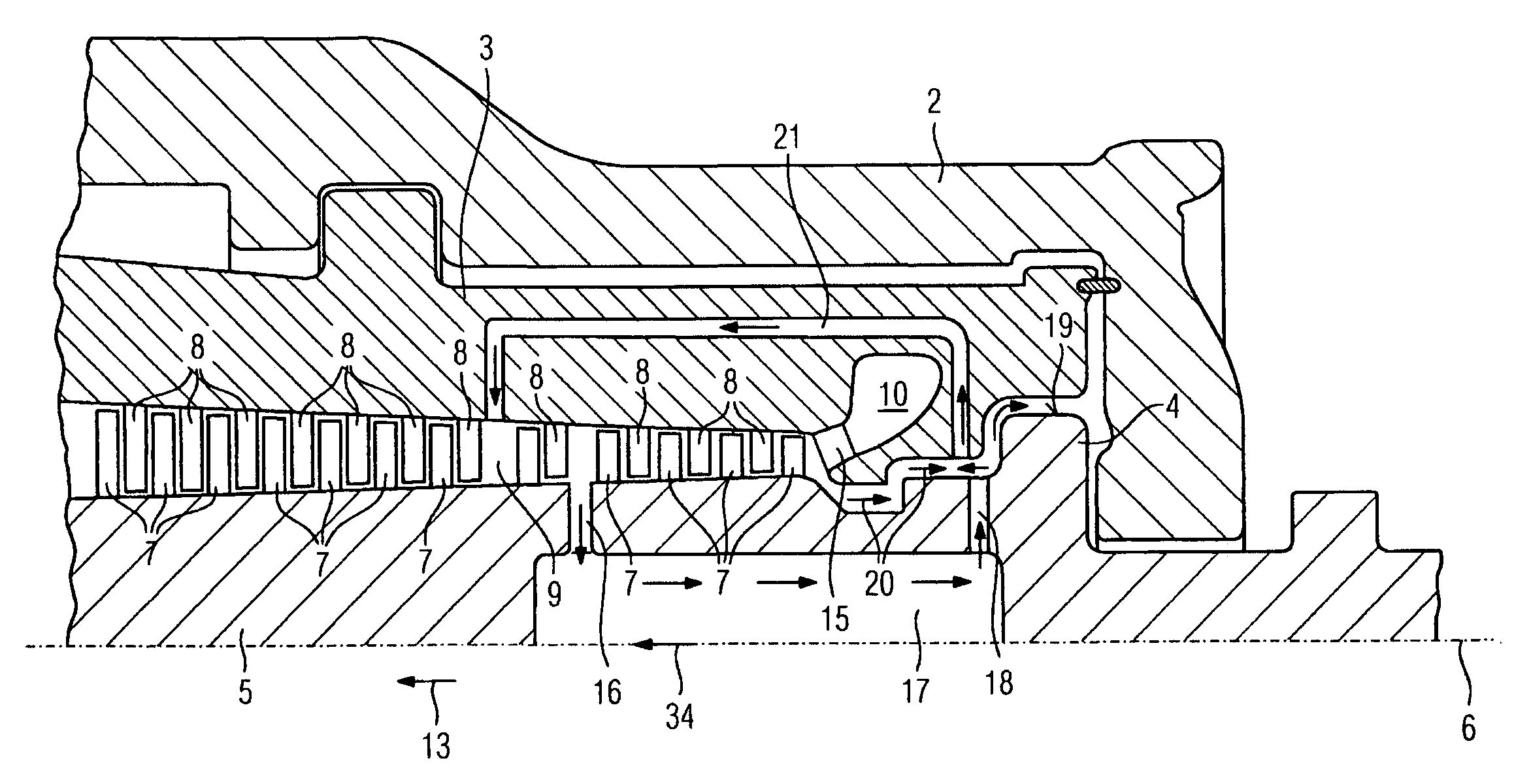
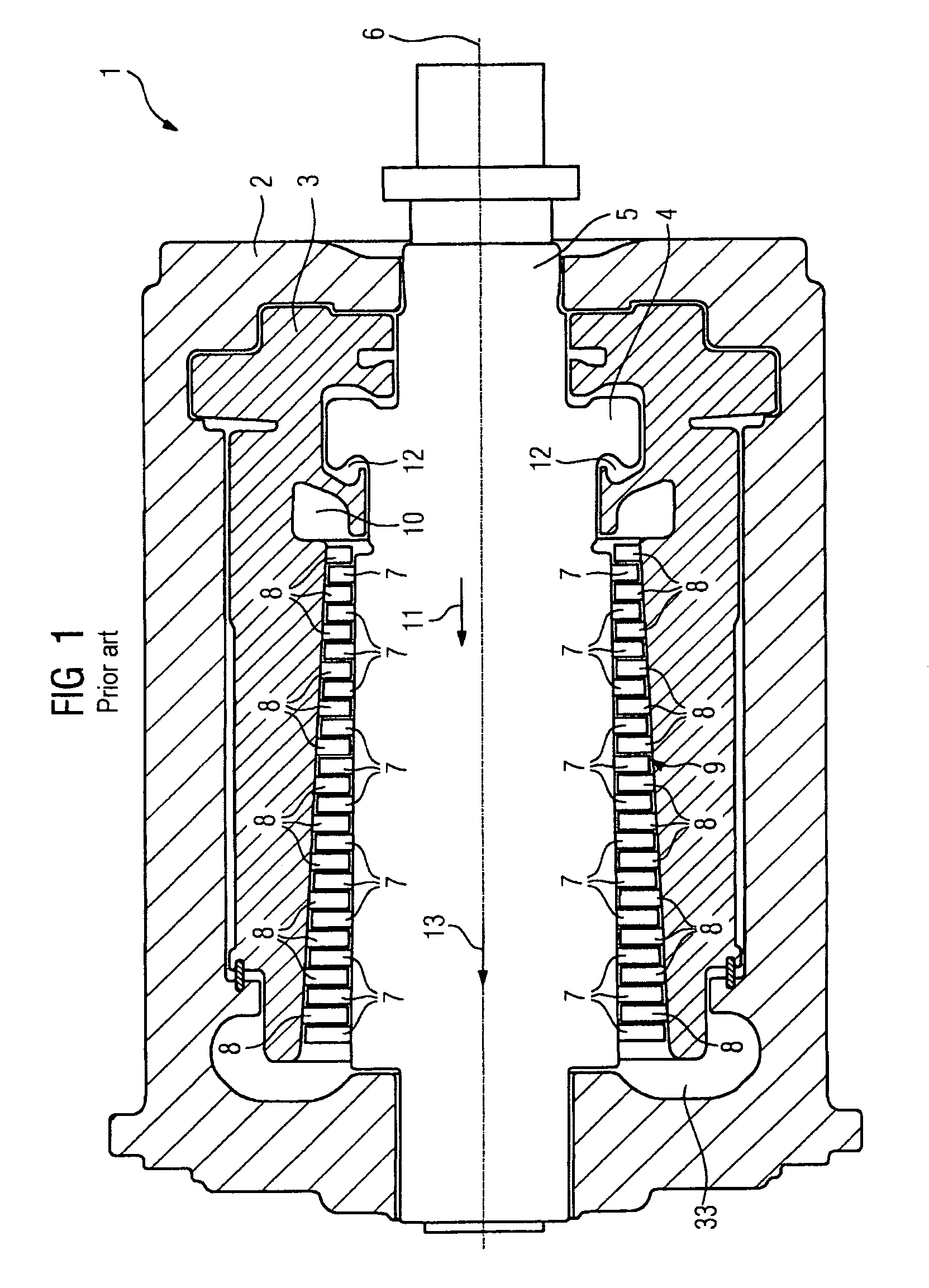
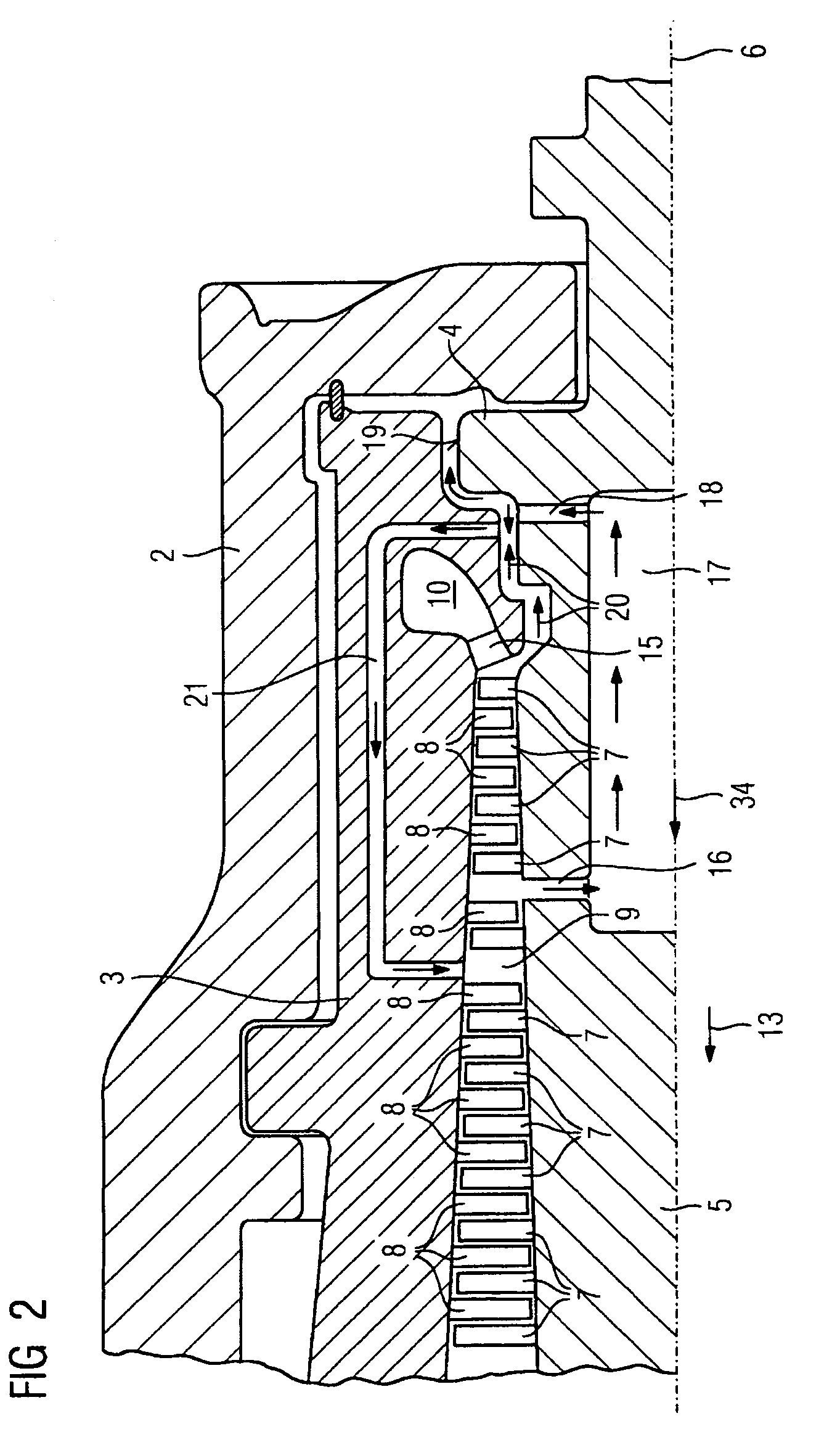
[0056]In FIG. 1, a section through a high-pressure turbine section 1 according to the prior art is shown. The high-pressure turbine section 1, as an embodiment of a steam turbine, comprises an outer casing 2 and an inner casing 3 which is arranged therein. Inside the inner casing 3, a turbine shaft 5 is rotatably mounted around a rotational axis 6. The turbine shaft 5 comprises rotor blades 7 which are arranged in slots on a surface of the turbine shaft 5. The inner casing 3 has stator blades 8 which are arranged in slots on its inner surface. The stator blades 8 and rotor blades 7 are arranged in such a way that a flow passage 9 is formed in a flow direction 13. The high-pressure turbine section 1 has an inlet region 10 through which live steam flows into the high-pressure turbine section 1 during operation. The live steam can have steam parameters of over 300 bar and over 620° C. The live steam, which expands in the flow direction 13, flows in turn past the stator blades 8 and rot...


PUM


Abstract

Disclosed is a steam turbine with a casing, wherein a turbine shaft having a thrust-compensating piston is rotatably mounted inside the casing and directed along a rotation axis, wherein a flow passage is formed between the casing and the turbine shaft. The turbine shaft has in its interior a cooling line for directing cooling steam in the direction of the rotation axis. The cooling line, on one end, is connected to at least one inflow line for the inflow of cooling steam into the cooling line from the flow passage, and on the other end, is connected to an outflow line for directing cooling steam onto a lateral surface of the thrust-compensating piston. An essential aspect is, the cooling steam discharging onto the lateral surface of the thrust-compensating piston mixes with some of the live steam and is directed back into the flow passage via a return line arranged in the casing.

Description

CROSS REFERENCE TO RELATED APPLICATIONS[0001]This application is the US National Stage of International Application No. PCT / EP2006 / 067717, filed Oct. 24, 2006 and claims the benefit thereof. The International Application claims the benefits of European application No. 05023760.1 filed Oct. 31, 2005, both of the applications are incorporated by reference herein in their entirety.FIELD OF INVENTION[0002]The invention relates to a steam turbine with a casing, wherein a turbine shaft, which has a thrust compensating piston, is arranged in a rotatably mounted manner inside the casing and is oriented along a rotational axis, wherein a flow passage is formed between the casing and the turbine shaft, wherein the turbine shaft has a cooling line within it for guiding cooling steam in the direction of the rotational axis, and the cooling line is connected to at least one inflow line for inflow of cooling steam from the flow passage into the cooling line.BACKGROUND OF THE INVENTION[0003]The us...

Claims


Application Information

Patent Timeline
Patent Type & Authority Patents(United States)
IPC IPC(8): F01D3/02F01D3/04
CPCF01D3/04F01D5/085F05D2260/2322F01D25/12F01D25/24
Inventor WIEGHARDT, KAI
Owner SIEMENS AG
Why Eureka
Try Eureka