Low mass fan shroud with integrated membrane barrier

a technology of low-mass fan and membrane barrier, which is applied in the direction of machines/engines, stators, liquid fuel engines, etc., can solve the problems of affecting the cooling performance of the fan module, and affecting the cooling performance of the material at elevated temperatures. achieve the effect of reducing the amount of material in the skir

a technology of low-mass fan and membrane barrier, which is applied in the direction of machines/engines, stators, liquid fuel engines, etc., can solve the problems of affecting the cooling performance of the fan module, and affecting the cooling performance of the material at elevated temperatures. achieve the effect of reducing the amount of material in the skir

US8128358B2Active Publication Date: 2012-03-06SIEMENS VDO AUTOMOTIVE INC

Image

  • Low mass fan shroud with integrated membrane barrier
  • Low mass fan shroud with integrated membrane barrier
  • Low mass fan shroud with integrated membrane barrier

Examples


Embodiment Construction

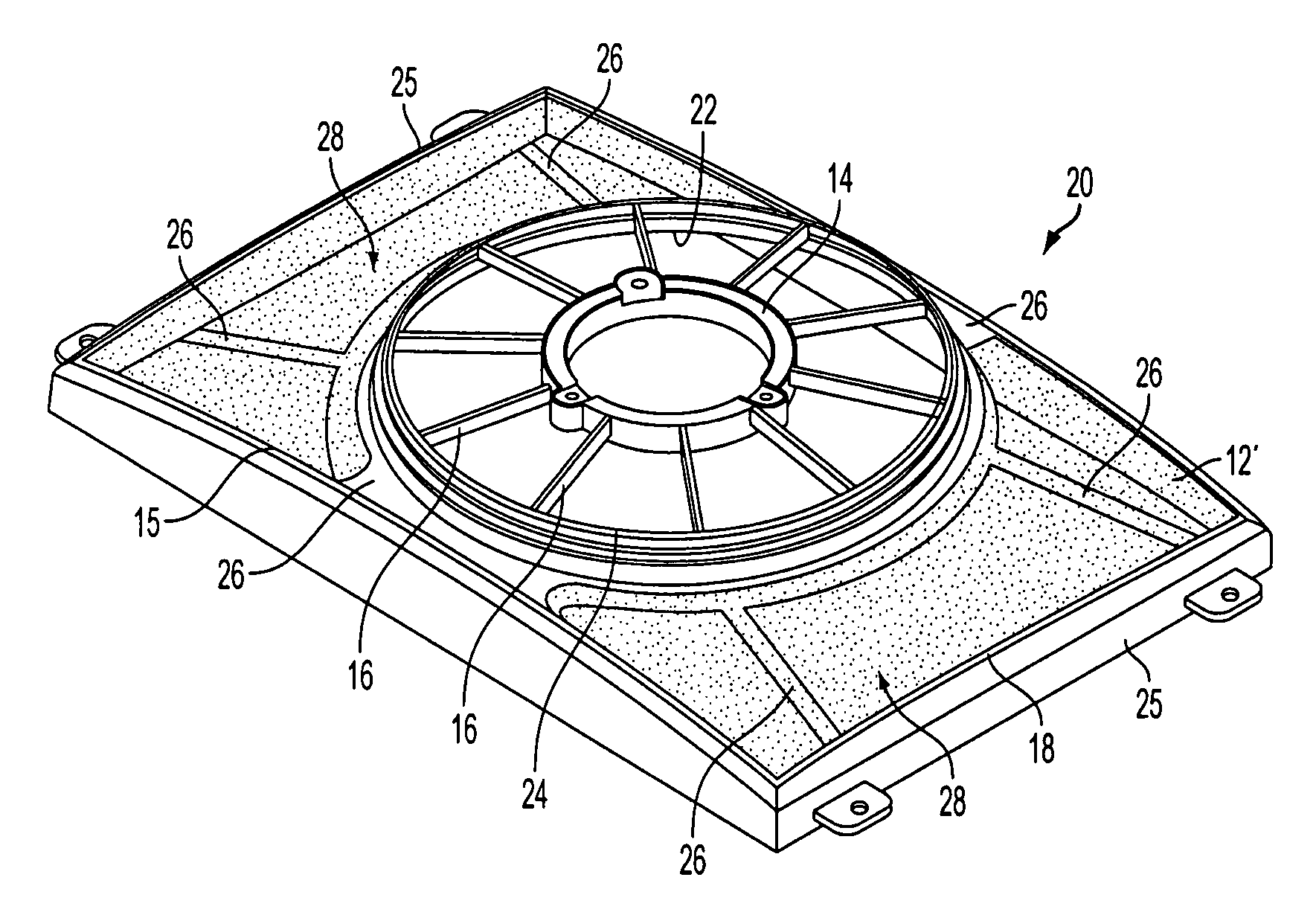
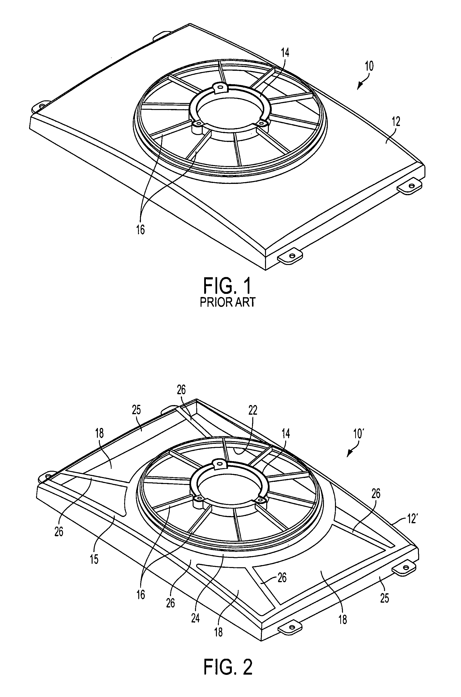
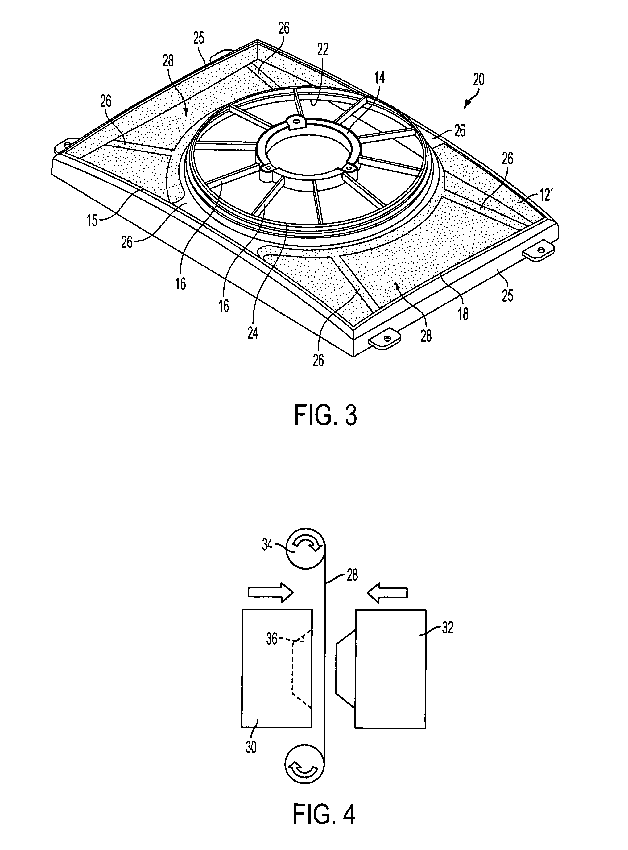
[0019]With reference to FIG. 2, a shroud, generally indicated at 10′, is shown in accordance with an embodiment of the invention. The entire shroud skirt 12′ does not need to be formed entirely from plastic resin to meet the functional requirements of the cooling module. Thus, the skirt 12′ has a generally box-like rectangular frame defining an outer surface 15 and annular rim 24 (e.g., shroud barrel) defining annular opening 22 therein that permits air to pass through the skirt 12′. A motor mount structure 14 is supported in the opening 22 and is constructed and arranged to permit a fan motor (not shown) to be mounted thereto in the conventional manner for generating airflow. The motor mount structure 14 is coupled with the annular rim 24 of the skirt 12′ via a plurality of arms 16. The annular rim 22 is secured to the skirt 12′ by support members 26. Thus, as in the embodiment of FIG. 2, the 2 mm wall stock is removed creating passageways 18 through the skirt 12′. The passageways ...


PUM

PropertyMeasurementUnit
thicknessaaaaaaaaaa
thickaaaaaaaaaa
thicknessaaaaaaaaaa

Abstract

An engine cooling fan shroud structure (20) for a vehicle includes a skirt (12′) defining a frame. The frame has a certain wall thickness and defines an opening (22) therein constructed and arranged to permit air to pass through the skirt. The skirt includes motor mount structure (14) supported in the opening and constructed and arranged for mounting a fan motor thereto. The frame defines passageways (18) there-through to reduce an amount of material of the skirt. A film material (28) has a wall thickness substantially less than the certain wall thickness and covers the passageways such that air may flow mainly through the opening.

Description

[0001]This application claims the benefit of the earlier filing date of U.S. Provisional Application No. 60 / 826,624, filed on Sep. 22, 2006, which is incorporated by reference herein in its entirety.FIELD OF THE INVENTION[0002]This invention relates to a low mass, automotive engine cooling fan shroud preferably molded from plastic.BACKGROUND OF THE INVENTION[0003]With reference to FIG. 1, a conventional plastic automotive cooling fan shroud is shown generally indicated at 10. The shroud 10 is of box shape having a skirt 12 and a motor mount 14 coupled to the skirt by a plurality of arms 16. The skirt 12 is solid and encloses the entire area of a radiator core to which the skirt 12 is mounted.[0004]A number of techniques have been used to improve performance or reduce shroud mass of the conventional shroud. Some suppliers of cooling fan modules remove a shroud skirt entirely and use only a ring shroud and support beams to hold the cooling fan in position behind the radiator. Although...

Claims


Application Information

Patent Timeline
06 Mar 2012
Publication
US8128358B2
IPC
F01P11/10
CPC
B29C45/14016; F04D29/526; B29C2045/1404
Inventors
MCLENNAN, PAUL STEPHEN