Surgical instrument for detecting, isolating and excising tumors

a surgical instrument and tumor technology, applied in the field of cutting surgical instruments, can solve the problems of physical ordeal for patients, increased risk of bleeding and infection, and compromise of cosmetic outcome of procedures, and achieve the effect of accurately positioning the device in alignment with the tumor

Inactive Publication Date: 2012-03-06
KENNEDY JOHN S
View PDF30 Cites 4 Cited by
  • Summary
  • Abstract
  • Description
  • Claims
  • Application Information

AI Technical Summary

Benefits of technology

[0012]Another feature of the surgical instrument may be the use of a detection probe such as an ultrasound instrument in concert with the other elements of the device. The device may be open-ended and sized and shaped for telescopically receiving the detection probe or some other detection device, so that the detection probe may be positioned in contact with the tissue of the patient where the tumor is located for reading the precise position of the tumor. This tends to accurately position the device in alignment with the tumor. Once the device is properly positioned, the detection device may be removed during the remainder of the surgical procedure, or may remain in place in the device to continuously check the location of the tumor as the incision is formed.

Problems solved by technology

One option for achieving a clear margin would be to remove a much larger amount of tissue about the tumor, however this compromises the cosmetic outcome of a procedure which is intended to conserve the contour of the breast.
The risk of bleeding and infection is likely increased as well.
Reexcision usually is demoralizing and a physical ordeal for the patient, let alone the costs, added recovery time, and added risks of a second procedure.

Method used


Image

  • Surgical instrument for detecting, isolating and excising tumors
  • Surgical instrument for detecting, isolating and excising tumors
  • Surgical instrument for detecting, isolating and excising tumors

Examples


Embodiment Construction

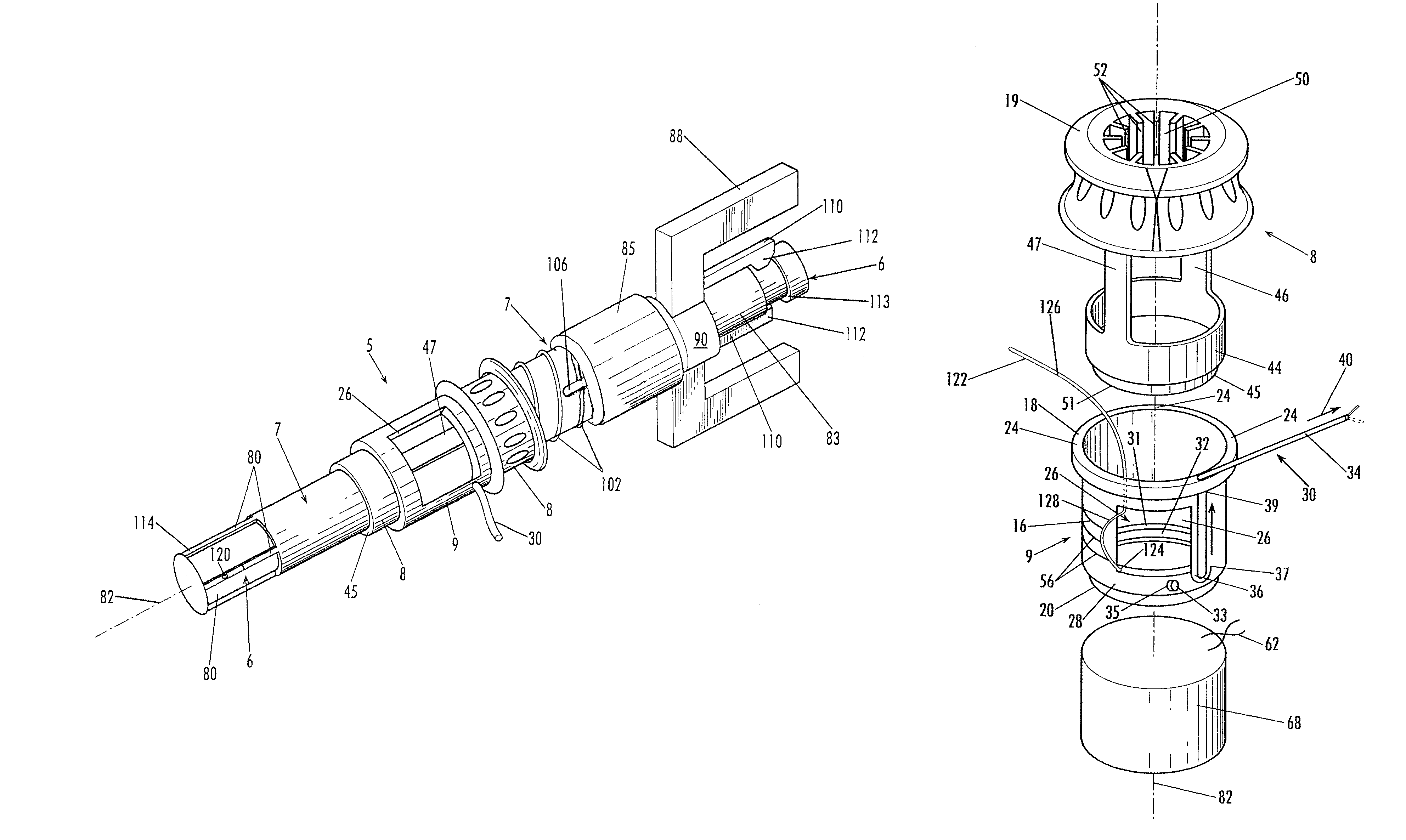
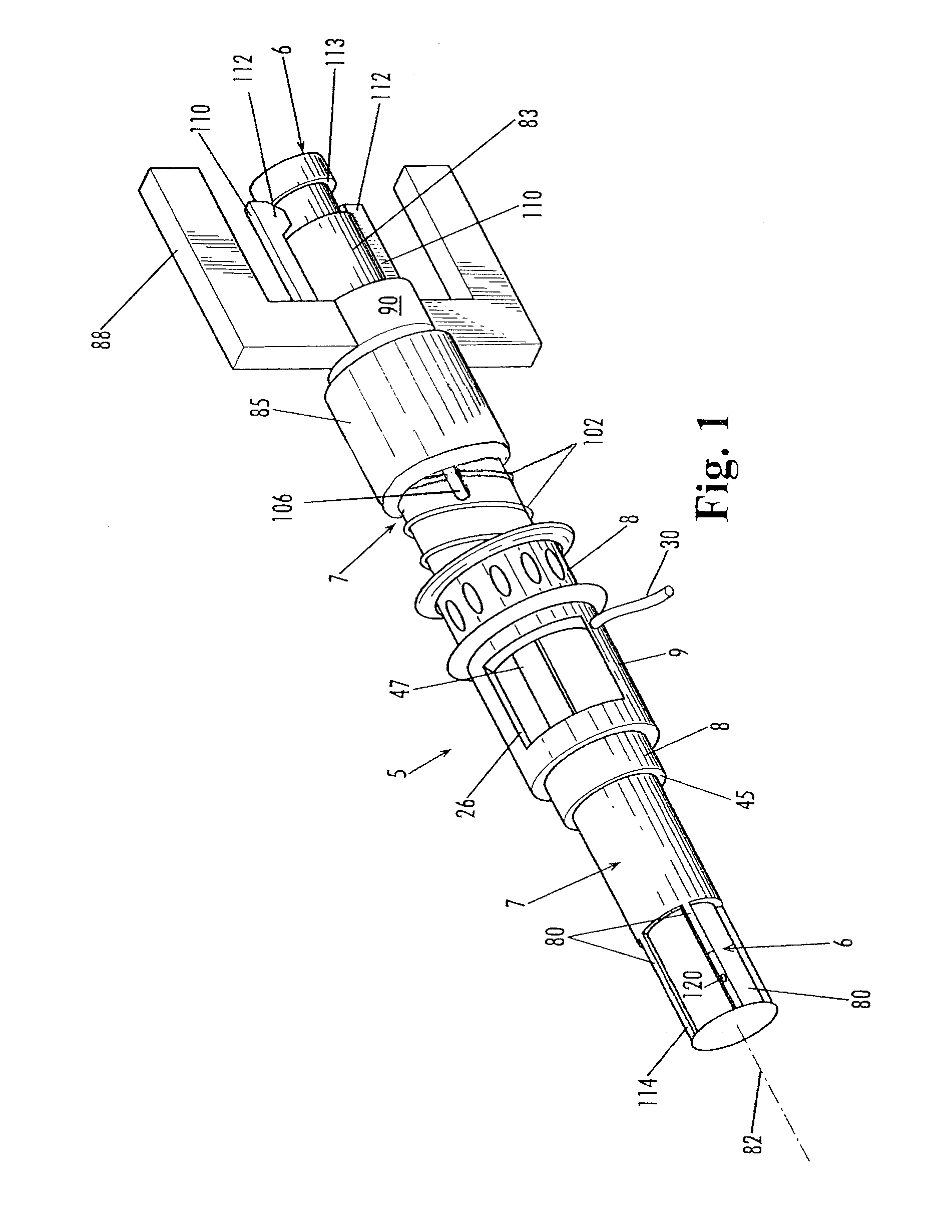
[0030]Referring now in more detail to FIG. 1, the assembled surgical instrument 5 includes an elongated detection probe such as an ultra sound instrument 6, a tubular carrier 7, a cutter 8 and a cannula 9. The tubular carrier 7, cutter 8 and cannula 9 may all be open ended and fit telescopically with respect to one another and telescopically about the detection probe 6, with the detection probe on the inside, the tubular carrier 7 next, the cutter 8 next, and the cannula 9 on the outside. The tubular carrier 7 is elongated and has an inner wall surface that telescopically fits about the detection probe so that the tubular carrier and the detection probe may be moved with respect to each other. Likewise, the cutter 8 and cannula 9 are shaped and dimensioned to be movable with respect to each other and movable about the tubular carrier.

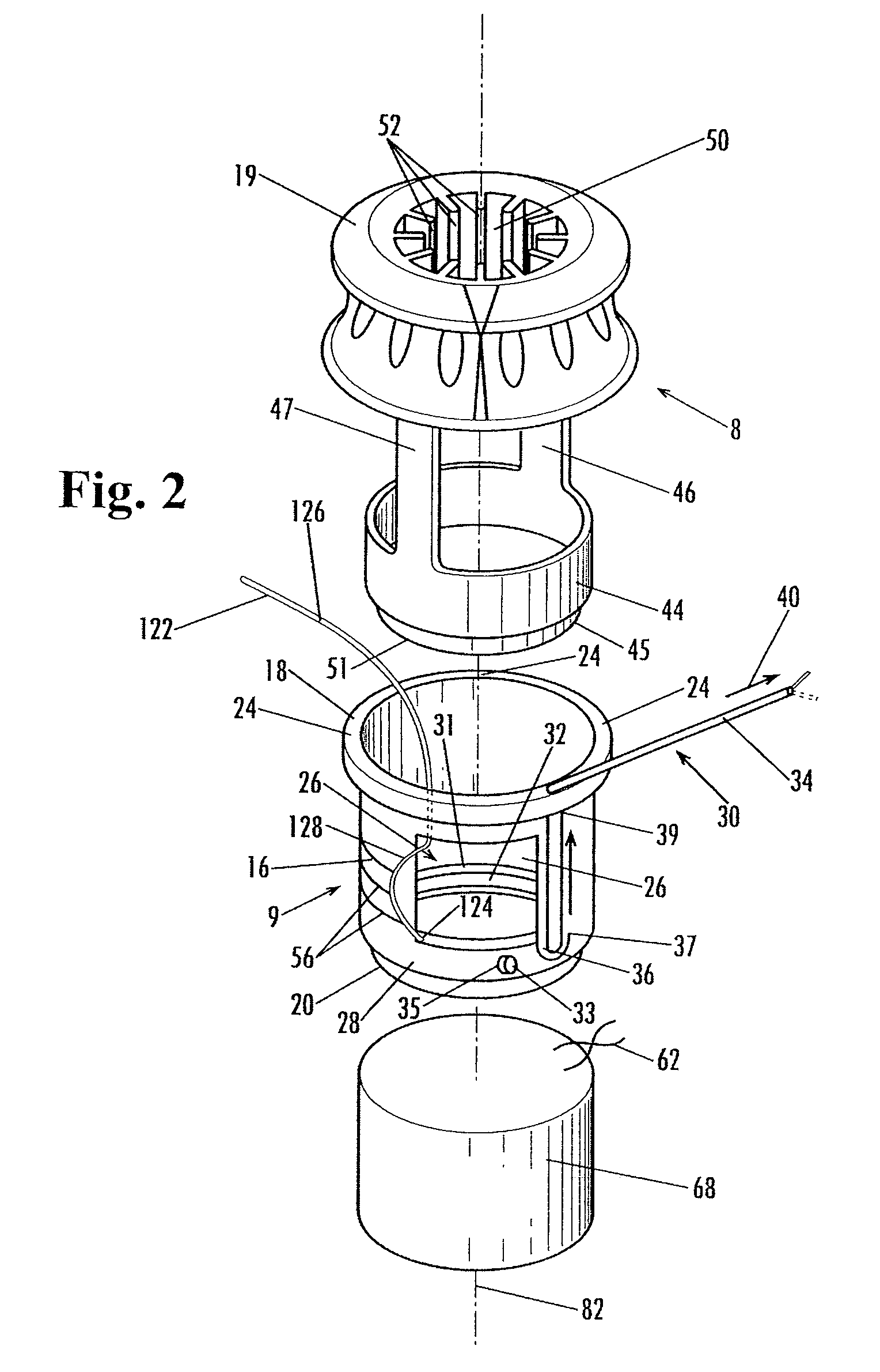
[0031]As shown in FIGS. 2 and 3, the cannula 9 includes a cylindrical sidewall 16, a proximal end 18, and a distal end 20. The proximal end 18 includes...


PUM


Abstract

A cutter (8) is telescopically received in a cannula (9) and both the cutter and cannula are telescopically mounted on a tubular carrier (7). A detection device (6) may be inserted through the open-ended carrier, cutter and cannula to properly place the surgical instrument in alignment with the tumor to be excised. Positioning tines (80) may penetrate the patient to firmly locate the carrier in its proper position on the patient. The cutter and cannula are moved about the carrier and are pressed into the tissue of the patient with the expectation that the circular core (60) of breast tissue formed by the cutter will have clear margins about the tumor. If the tumor extends too close to the circular incision, the cannula may be rotated so that its sidewall opening (26) faces the side of the remaining tissue to be excised and the surgeon can pull the remaining tissue through the sidewall and excise it, thereby avoiding a separate and delayed surgical procedure.

Description

CROSS REFERENCE[0001]This is a continuation-in-part of U.S. Utility patent application Ser. No. 11 / 939,587 filed Nov. 14, 2007 now abandoned.FIELD OF THE INVENTION[0002]This invention concerns a cutting surgical instrument used by a surgeon during the process of detecting, isolating and excising malignant or non-malignant tumors or other lesions from various parts of the body, particularly for use in lumpectomy, extracting cancerous tumors from the breast.BACKGROUND OF THE INVENTION[0003]When conducting breast surgery for the removal of tumors, the usual procedure is to locate the position and depth of the tumor by use of palpation, ultrasound, mammogram, or other detection devices. With this information, the surgeon typically makes a shallow incision in the skin so as to pull away the skin from the underlying tissue and then proceeds with surgery through the opening in the skin and into the fat and breast tissue to reach the tumor and excise it.[0004]In recent years, various surgic...

Claims


Application Information

Patent Timeline
Patent Type & Authority Patents(United States)
IPC IPC(8): A61B17/32
CPCA61B17/32053A61B17/3421A61B2017/008A61B2017/00991A61B2019/5276A61B2090/378
Inventor KENNEDY, JOHN S.
Owner KENNEDY JOHN S
Why Eureka
Try Eureka