Lens position detecting device including a position detecting magnet and a magnet force detecting sensor
a position detection and sensor technology, applied in the field of lens barrels, can solve the problems of reduced reliability of circuits and devices, increased sensor installation space, and inability to effectively utilize the space of the lens barrel
- Summary
- Abstract
- Description
- Claims
- Application Information
AI Technical Summary
Benefits of technology
Problems solved by technology
Method used
Image
Examples
embodiment 1
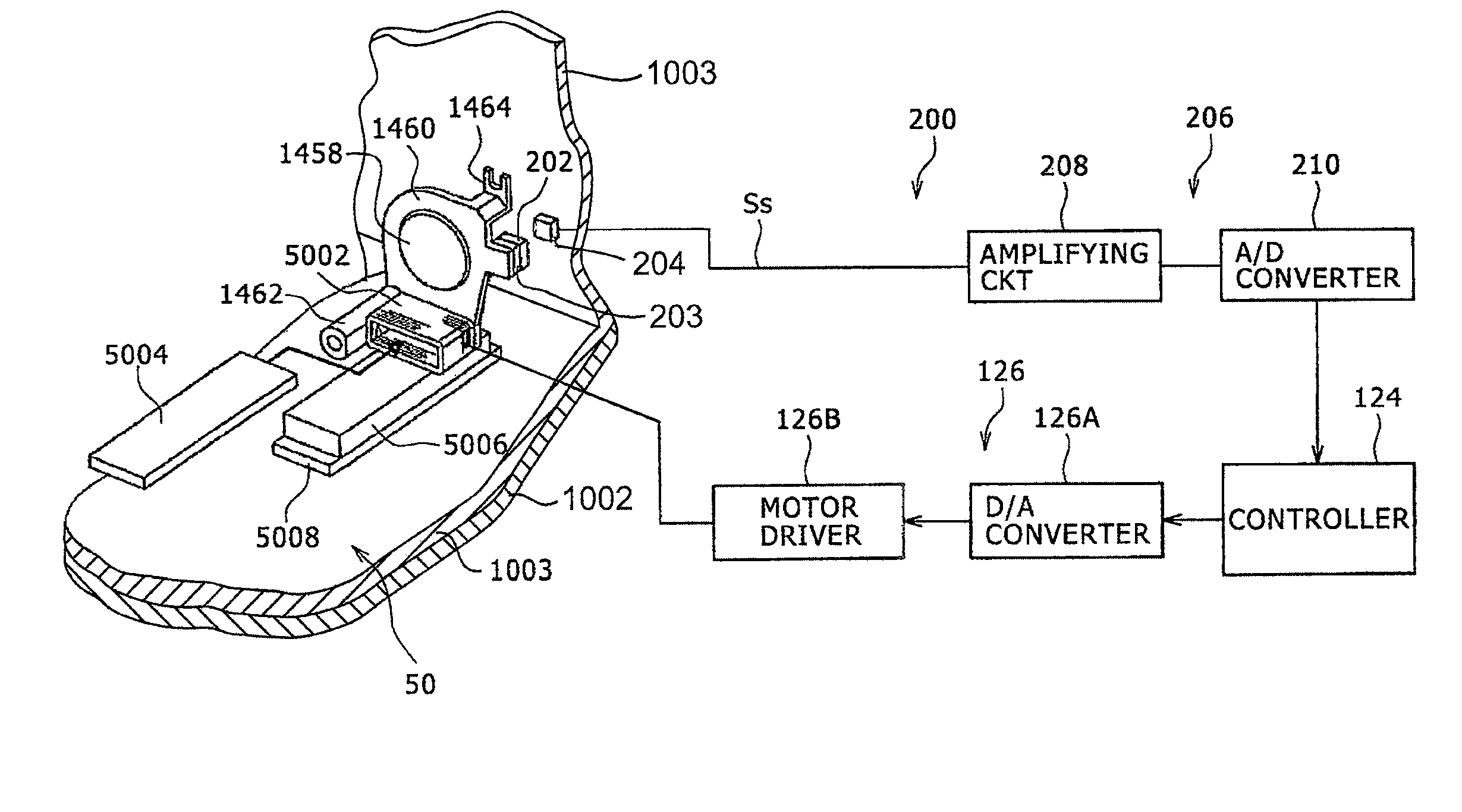
[0132]Embodiment 1 of the present invention will be described below with reference to the drawings.
[0133]A lens position detecting device according to the present invention as incorporated in a digital still camera which serves as an image capturing device will be described below.
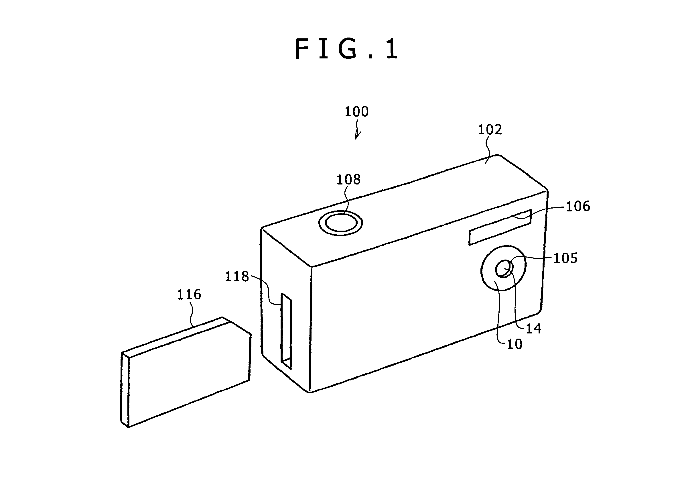
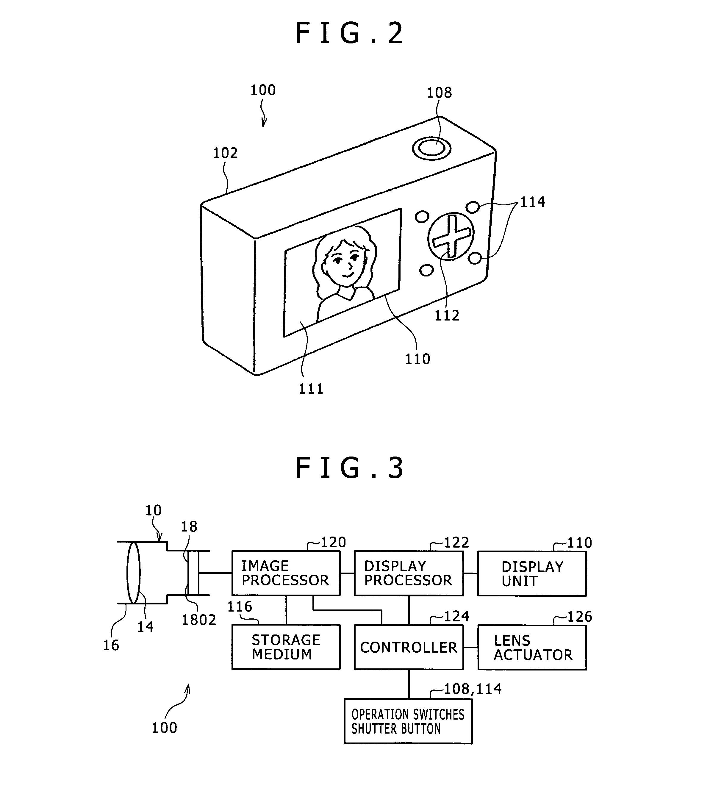
[0134]FIG. 1 is a perspective view of an image capturing device incorporating a lens position detecting device according to Embodiment 1, as viewed from front, FIG. 2 is a perspective view of the image capturing device according to Embodiment 1, as viewed from behind, FIG. 3 is a block diagram of a control system of the image capturing device, and FIG. 4 is a cross-sectional view of a lens barrel.
[0135]As shown in FIG. 1, an image capturing device 100 includes a digital still camera and has a case 102 in made up of rectangular plates serving as an outer housing. In the present embodiment, left and right are referred to with respect to the image capturing device 100 when it is viewed from front, and a subjec...
embodiment 2
[0187]Embodiment 2 will be described below.
[0188]Embodiment 2 differs from Embodiment 1 in that the magnitude of the amplification factor of the amplifying circuit 208 is capable of switching between two levels.
[0189]FIG. 7 is a view showing an arrangement of a lens guiding mechanism, a lens moving mechanism, and a lens position detecting device according to Embodiment 2, FIG. 8 is a diagram showing an arrangement of an amplifying circuit 208, and FIG. 9 is a diagram showing the relationship between a lens position and a detected signal according to Embodiment 2. In each of the embodiments described below, those parts and members which are identical to those of Embodiment 1 are denoted by identical reference characters.
[0190]As shown in FIG. 7, according to Embodiment 2, an amplifying circuit 208 includes first and second amplifiers 208A, 208B and a switch 208C.
[0191]The first amplifier 208A is supplied with the detected signal Ss from the magnetic force detecting sensor 204, and am...
embodiment 3
[0210]Embodiment 3 will be described below.
[0211]Embodiment 3 differs from Embodiment 1 as to the lens moving mechanism.
[0212]FIG. 11 is a view showing an arrangement of a lens guiding mechanism, a lens moving mechanism, and a lens position detecting device according to Embodiment 3.
[0213]A lens moving mechanism 50′ includes an actuating coil 5022, an opposite yoke 5024, an actuating magnet 5026, and a ground yoke 5028.
[0214]The actuating coil 5022 is wound around an axis parallel to the optical axis and fixed by an adhesive or the like to the lower surface of an attachment arm 1461 which projects from a lower portion of the lens holder frame 1460 (forwardly) in an optical axis direction.
[0215]The opposite yoke 5024 is inserted in an opening defined in a portion of the lens holder frame 1460 above the attachment arm 1461 and extends parallel to the optical axis.
[0216]The actuating magnet 5026 is in the shape of a strip, and is disposed on an outer circumferential surface of the actu...
PUM
 Abstract
Description
Claims
Application Information
 - R&D
- Intellectual Property
- Life Sciences
- Materials
- Tech Scout
- Unparalleled Data Quality
- Higher Quality Content
- 60% Fewer Hallucinations
Browse by: Latest US Patents, China's latest patents, Technical Efficacy Thesaurus, Application Domain, Technology Topic, Popular Technical Reports.
© 2025 PatSnap. All rights reserved.Legal|Privacy policy|Modern Slavery Act Transparency Statement|Sitemap|About US| Contact US: help@patsnap.com


