Space based rotating film solar battery array

a solar battery array and rotating film technology, applied in the field of solar battery array construction, can solve the problems of endangering the rotating tensile, and achieve the effects of enhancing power, reducing the launching weight of spacecrafts, and saving a remarkable launching cos

Inactive Publication Date: 2012-03-13
HUANG SHANGLI
View PDF5 Cites 7 Cited by
  • Summary
  • Abstract
  • Description
  • Claims
  • Application Information

AI Technical Summary

Benefits of technology

[0010]To adapt this invention for various spaceflight objects: a film solar battery array can be used in various space satellites which need high-power electric resource. The satellites need detecting sunlight-direction can have a center axle directly saddled on their shell (cylindrical type of body); other direction detecting models (like global positioning satellites) can link a universal holder to a foldable pole-support which links to the center axle. Thus, the satellites and the film solar battery array can position their own direction respectively. Satellites, which adopt the later model with a foldable pole-support, may minimize their structure size as a whole before the launching time.
[0012]A thin film solar battery array may be utilized in a solar energy powered rocket: at present ion propeller has been widely used in the satellite's attitude control and track maintenance. The US Aerospace Bureau's “Deep Space 1st Detector”, launched in 1998, and The European Astronautics Bureau's “SMART-1 lunar probe”, launched in 2003, both use ion propeller to push the engine for the last stage host. Now these two detectors have completely experimented through the test plan that proves the long-lasting reliability that an ion rocket engine can make. At present, the bottleneck for the electric power is to enhance the thrust force with an ion engine. The specific energy produced from an existing solar batteries wind surf board is too low, (approximately 40 tiles / kilograms); it can not provide formidable electric power. To enlarge the area size for the solar wind surf board is not only to increase the weight greatly, but also with difficulty to meet the structural strength required for the board. But a thin film solar battery array has got high specific energy (approximately 10 times to the former one), moreover, it is maintained by cables and thin film tensity (self-rotating to produce centrifugal force), can endure bigger impulse and acceleration, extremely suits for a high-efficiency electric rocket. A solar electric rocket equipped with a thin film battery array as the last stage rocket, might send a large-scaled satellite or spaceship from low Earth orbit to high orbit, even to interplanet space. Because electrically-powered rockets' “specific impulse” is 10 times higher than a chemical rockets, it may save massive fuels. Using a solar electric rocket as the last stage rocket will greatly reduce weight from the front stage rocket, and so saves launching expense. A high-efficiency electrically-powered rocket equipped with a thin film solar battery array is especially suitable for a deep space survey, human Moon-landing and long-range flight to Mars. The high-efficiency solar electric rocket may serve as an orbital transfer vehicle (OTV) for a long-term movement along the Earth orbit. It is applied in changing satellite's track too. For example it will push a spacecraft from a lower Earth orbit up to high orbit, even to a geosynchronous Earth orbit.
[0014]The unit-area weight of a thin film solar battery array is very light, only 1 / 30 to 1 / 100 weight to a traditional solar cell wind surf board, that will greatly reduce the launching-weight for spacecrafts and so save a remarkable launching-cost.
[0016]The sufficient electric power generated from a thin film solar battery array may enhance the power dozens of times for the television direct transmission satellite and the communications satellite.
[0017]A thin film solar battery array can endure greater acceleration and impulse. During spacecraft accelerating or changing orbit flight, it is unnecessary to coil the battery array, especially suitable for a solar energy electrically-powered rocket. Satellites equipped with a solar energy electrically-powered rocket may greatly enhance the ability to maintain on orbit and the capability to maneuver, and double the length of service life. Deep space detectors and spaceships equipped with a high efficiency solar energy electrically-powered rocket may remarkably enhance navigation speed, reduce survey cycle or round-trip time.

Problems solved by technology

Secondly, it endures rotating tensile force coming from the film battery array.

Method used


Image

  • Space based rotating film solar battery array
  • Space based rotating film solar battery array
  • Space based rotating film solar battery array

Examples


implementation example 1

A Battery Array is Made of Rectangle Film Solar Batteries

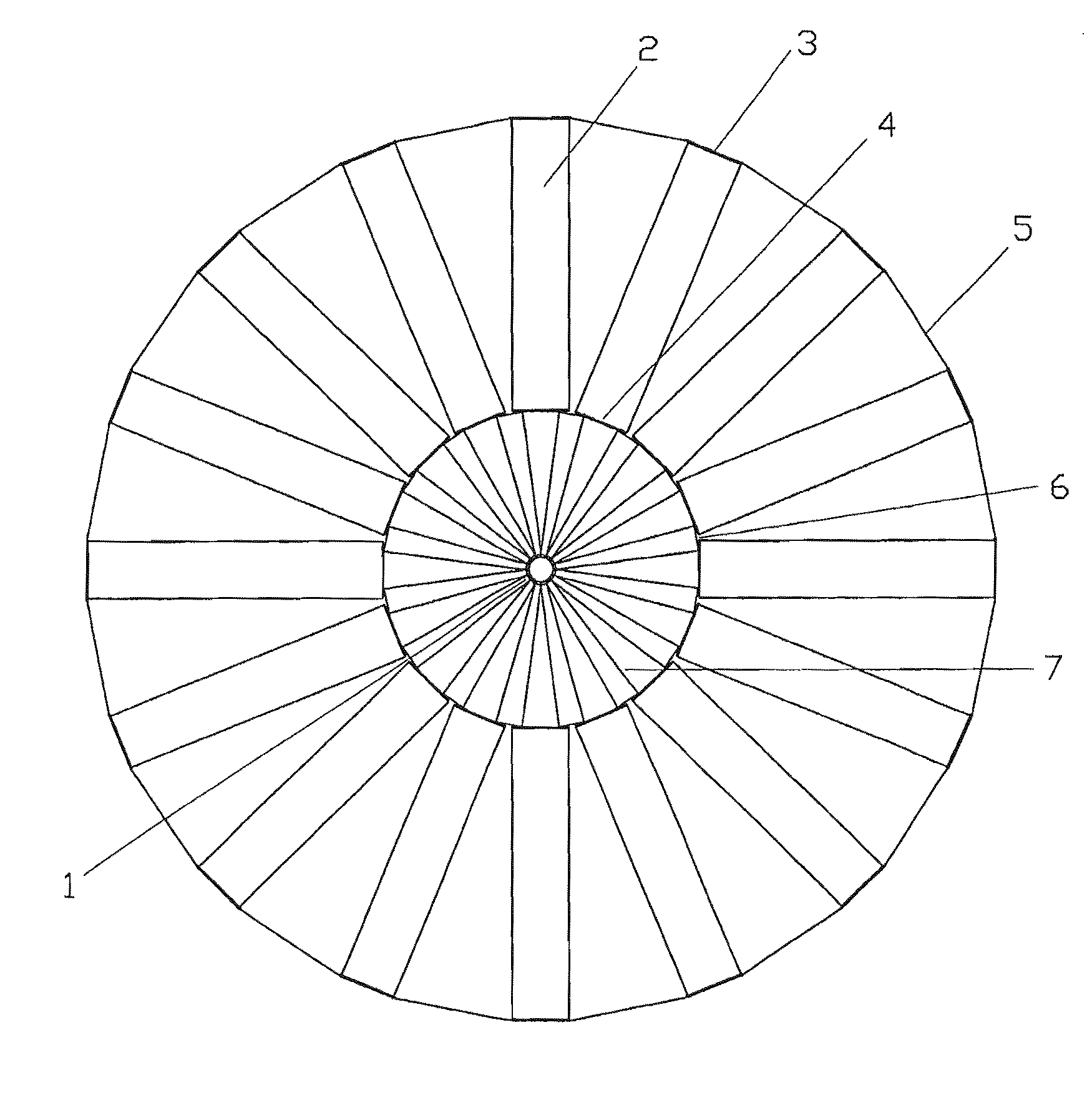
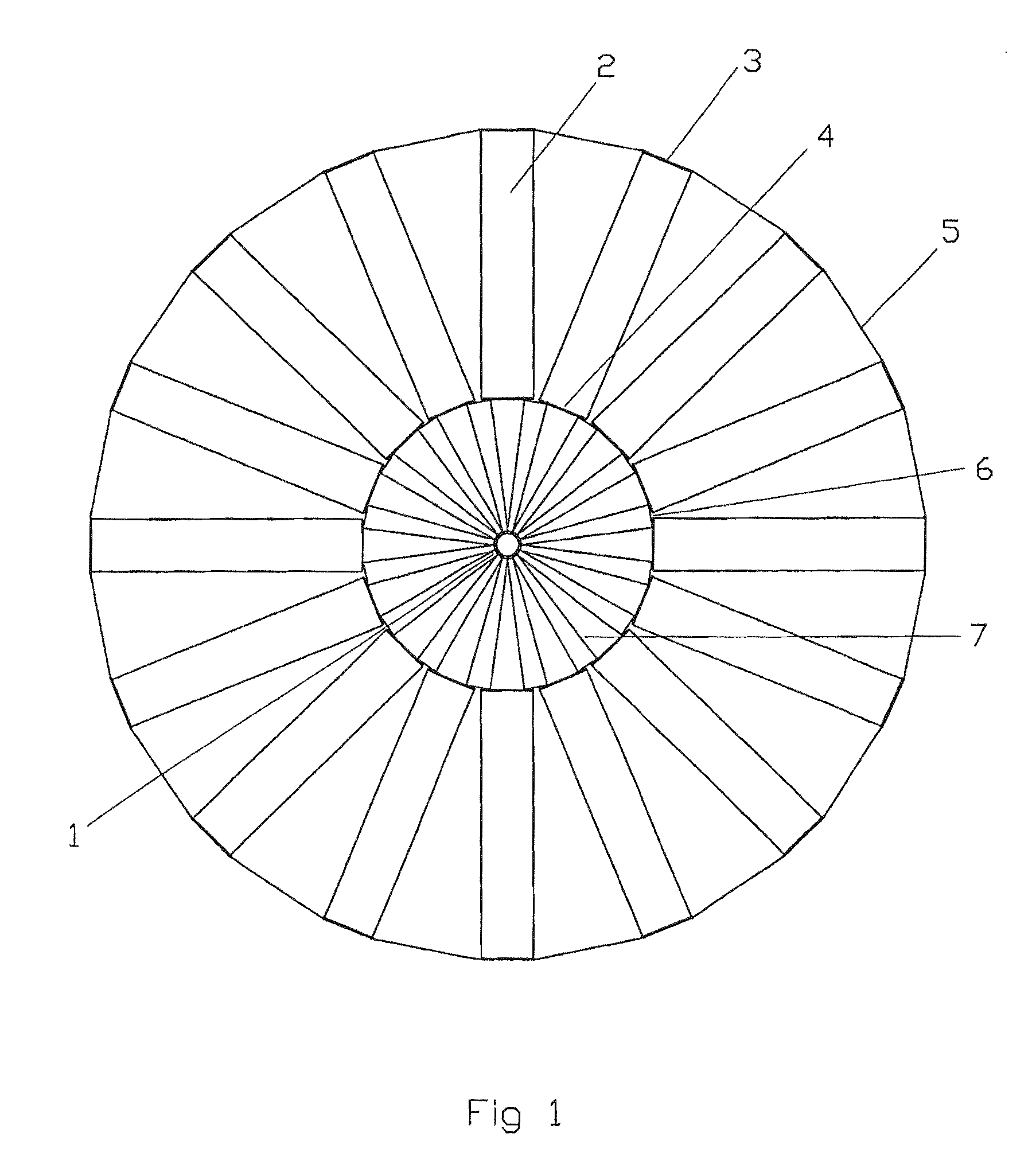
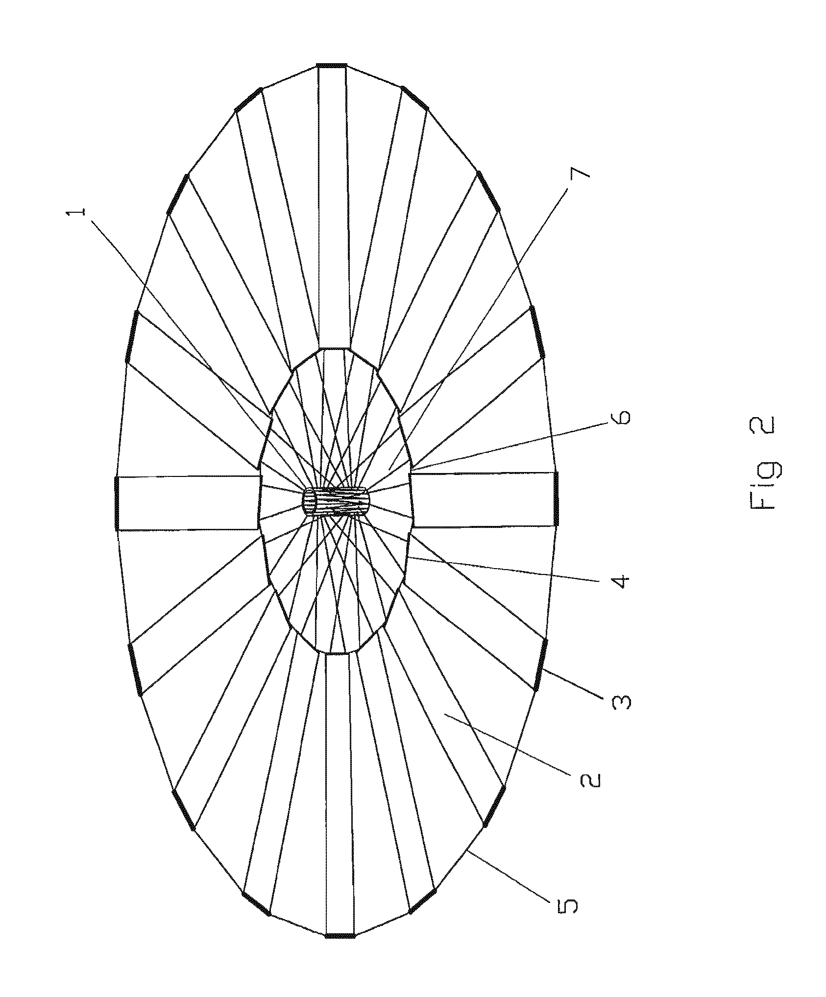
[0039]FIG. 1 shows top-view of a completely deployed rectangular thin film battery array. The center axle (1) located at the middle battery array. The thin film batteries (2) (16 spokes) radiates out to form a circular shaped array. The neighboring thin film batteries are connected with outside ring cable (5) and inside ring cable (6). Near the center array, one end of each thin film battery array connects the center axle (1) with electrical cable (7) (this example has 32 cables). The thin film battery (2) has outside reinforcing rod (3) and inside reinforcing rod (4) at both end, used to protect the thin film battery and control thin film's direction. FIG. 2 is a three-dimensional schematic drawing for the thin film solar battery array described above, (All attached numbering figures are consistently used in this instruction booklet. The names of various components in the figure are not given unnecessary details.) FIG. 2 show...

implementation example 2

A Battery Array Constructed by Fan-Shaped Thin Film Batteries

[0049]FIG. 3 shows the front-view of a completely deployed fan-shaped thin film battery array: the fan-shaped thin film solar batteries (8) spoke to form a circular. The neighboring thin film batteries are connected with outer ring (5) and inner ring cable (6). Near the center of the array, the thin film battery has inside reinforcing rod (4). Both sides of reinforcing rod have electrical able (7) connecting to the center axle (1). (Because two end sides of neighboring inside reinforcing rods are too close, electrical cables leading out from two ends form a y-shaped connecting cable which in FIG. 3 shows.

[0050]FIG. 4 is a completely deployed three-dimensional schematic drawing of a fan-shaped thin film battery array: obviously unlike a rectangular thin film battery array, electrical cable (7) is completely set in a plane with the thin film battery, therefore the thin film battery inclining angle is unable to adjust, also u...

implementation example 3

The Plan to Reduce Center Axle Diameter

[0052]In the most situations, a center axle certainly is not a spacecraft's main body. Fitting into a spacecraft to carry before lifting off, a thin film battery array should minimize its size by reducing the diameter of the center axle as much as possible. When the center axle diameter is 5% smaller than the thin film battery array's diameter after its deployment, the control to the thin film battery array action is very weak. In order to solve this problem, it may use one kind of structure similar to umbrella skeleton inside the center axle. Like FIG. 11 shows: the center axle (43) exterior is a tall and slender cylindrical shell, the umbrella column (44) passing through the center of the center axle (43), setting with an upper plate at its top (18), the umbrella bone (19) connecting to the upper plate (18) with a hinge joint, and the electrical cable plate (10) is harnessed on the axle of the hinge. The umbrella bone (19) is a hollow tube, m...


PUM


Abstract

A self rotating deployed film solar battery array includes film solar batteries, electrical cables, a center axle and connecting lines. A plurality of long strip shaped film solar batteries radiate to form a circle or a polygon-array. Two adjacent film solar batteries are linked by connecting lines. Each film solar battery is linked to the center axle by electrical cables. The film solar batteries are deployed and maintained in an array shape by a self rotating centrifugal force in space. The film solar batteries are coiling outside the surface of the center axle before their deployment. The unit weight of a thin film battery is only 1 / 30 of a traditional solar cell paddle.

Description

FIELD OF THE INVENTION[0001]This invention is about the construction of a solar battery array used in spaceflight—more detailed about the device utilized to control a spaceflight's soft film solar battery array which is foldable an deployable in spaceflight applications.BACKGROUND ART[0002]Most current spaceflights adopt solar energy powered battery. A solar battery array can be installed either inside the spaceflight or outside in a form sail board. The solar-direction-detecting sail board batteries can provide more resource of electric power than batteries. In order to increase energy density out of a solar battery array, Hughes Aircraft Company has selected “soft folding solar batteries sail” (see, Space Station and Space Platform, pages 396-97). In order to deploy this kind of soft sail, the need of installing a solid holder and a limit of its size eventually becomes inevitable—energy density is not high enough (47 w / kg)—therefore the “soft coiling solar batteries sail” has not ...

Claims


Application Information

Patent Timeline
Patent Type & Authority Patents(United States)
IPC IPC(8): B64G1/44H02S30/20
CPCB64G1/222H02S30/20B64G1/44B64G1/425Y02E10/50
Inventor HUANG, SHANGLI
Owner HUANG SHANGLI
Why Eureka
Try Eureka