An antenna radio frequency front-end device with direction finding and active anti-jamming functions
A radio frequency front-end and antenna technology, which is applied in the field of antenna radio frequency front-end devices, can solve the problems of increasing receiving gain and coverage distance, blocking receivers, and analog filters cannot be filtered out, so as to improve the linear dynamic range and minimize the structure size Effect
- Summary
- Abstract
- Description
- Claims
- Application Information
AI Technical Summary
Problems solved by technology
Method used
Image
Examples
Embodiment 1
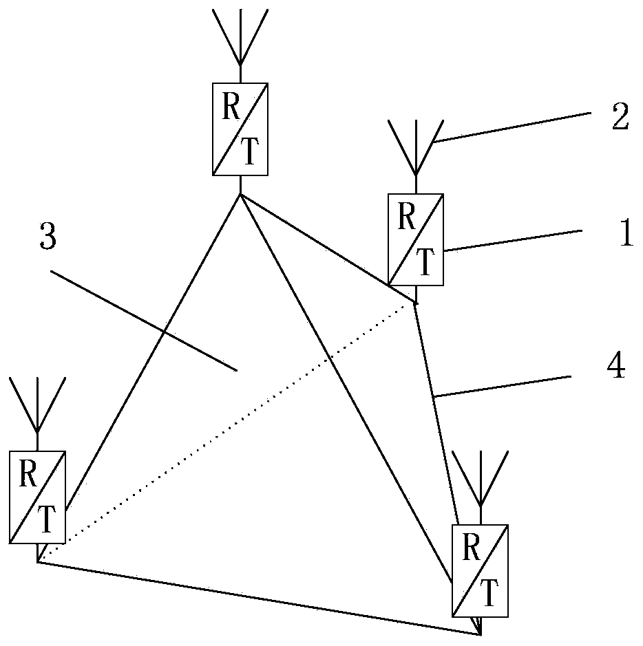
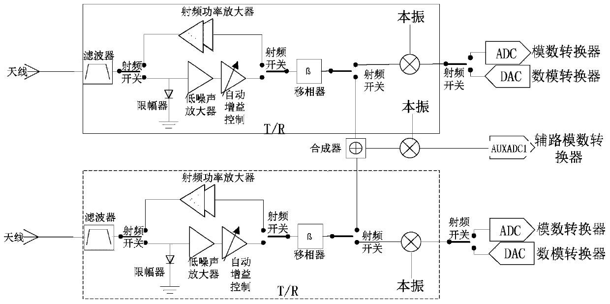
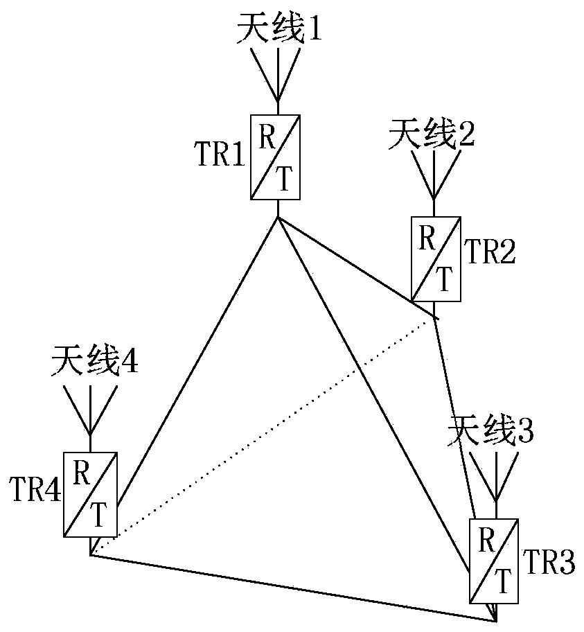
[0025] Embodiment one: image 3 It is a schematic diagram of the three-dimensional structure of the antenna radio frequency front-end device in the embodiment, Figure 4 for image 3 In the detailed expansion diagram on the two-dimensional plan, the four receiving channels are calibrated and compensated by the vector network analyzer. The measured phase error between each channel is less than 9°, and the cables are all equal-length, phase-stable RF cables. A sum and difference channel is set between TR1 and TR2, a sum and difference channel is set between TR3 and TR4, and there are two sets of sum and difference channels. The interference source is simulated by the signal source. The antenna adopts the same type of horizontal omnidirectional rod antenna, which are respectively placed on the four vertices of the regular tetrahedral frame structure. The edge length of the regular tetrahedral frame structure is half wavelength. Then, the signal source is used to transmit a per...
Embodiment 2
[0034] Embodiment two: if image 3 As shown, further verification tests were carried out with a swept frequency signal source. As above, set the signal source to emit 300MHz-600MHz sinusoidal signal at the same place to simulate the interference signal, and then use the spectrum analyzer to receive it under line-of-sight conditions. M1 and M2 in the figure represent test mark points 1 and 2 respectively. M1=375MHz, choose another mark point M2=535MHz to test, the combined power of the channel is about -6.9dBm under the condition of no phase shift, such as Figure 5 As shown; when the phase shift makes the phase difference close to 180°, the synthesized power is reduced to -32.73dBm, such as Figure 6 shown. Obviously, the interfering signal from the space can be reduced by nearly 26dB after phase shifting.
PUM
 Abstract
Description
Claims
Application Information
 - R&D
- Intellectual Property
- Life Sciences
- Materials
- Tech Scout
- Unparalleled Data Quality
- Higher Quality Content
- 60% Fewer Hallucinations
Browse by: Latest US Patents, China's latest patents, Technical Efficacy Thesaurus, Application Domain, Technology Topic, Popular Technical Reports.
© 2025 PatSnap. All rights reserved.Legal|Privacy policy|Modern Slavery Act Transparency Statement|Sitemap|About US| Contact US: help@patsnap.com


