
Shallow-water small micro-buoyancy photoelectric composite cable transmission assembly

A technology for optoelectronic composite cables and transmission components, applied in power cables, power cables including optical transmission components, electrical components, etc., can solve problems such as high cost, growth, and large cable resistance, and achieve increased tensile strength and resistance The effect of bending strength, extended service life, and simple assembly

Pending Publication Date: 2021-09-24
上海溪淇电子科技有限公司
View PDF0 Cites 0 Cited by
  • Summary
  • Abstract
  • Description
  • Claims
  • Application Information

AI Technical Summary

Problems solved by technology

[0003] At present, domestic optoelectronic hybrid transmission components have a large overall weight, large volume, large space occupation, and high cost, which cannot be well adapted to the current requirements for the use of such small-depth instruments and equipment. Therefore, a shallow water small micro Increasing demand for buoyancy optoelectronic composite cable transmission components
Most of the underwater photoelectric hybrid cables currently on the market have high density and heavy weight, which leads to relatively large resistance caused by the underwater self-weight of the cable during long-distance transmission. Therefore, a shallow water small-scale micro-buoyancy photoelectric Composite Cable Transmission Components

Method used


Image

  • Shallow-water small micro-buoyancy photoelectric composite cable transmission assembly
  • Shallow-water small micro-buoyancy photoelectric composite cable transmission assembly

Examples


Embodiment 1

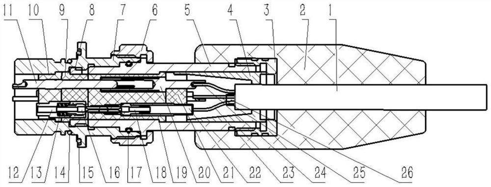
[0022] see Figure 1-2 , the present invention provides a technical solution:

[0023] A small micro-buoyancy photoelectric composite cable transmission assembly in shallow water, comprising a plug housing 5 and a socket housing 7, the outer left end of the plug housing 5 is provided with a connecting screw sleeve 6, and the outer left end of the plug housing 5 is provided with a first sealing ring 17. The inner right end of the plug housing 5 is provided with a plug front insulator 19 and a plug rear insulator 21, the outer right end of the plug housing 5 is provided with an injection molded elastomer 2, and the inner right end of the injection molded elastomer 2 is provided with a micro buoyancy The outer sheath 1 of the photoelectric composite cable, the inner side of the outer sheath 1 of the micro-buoyancy photoelectric composite cable is provided with a reinforced cladding 26, and the inner side of the reinforced cladding 26 is provided with a first optical fiber 23 and ...


PUM


Abstract

The invention relates to the technical field of underwater photoelectric composite cable transmission, in particular to a shallow-water small micro-buoyancy photoelectric composite cable transmission assembly which comprises a plug shell and a socket shell, a connecting thread sleeve is arranged at the left end of the outer side of the plug shell, and a first sealing ring is arranged at the left end of the outer side of the plug shell. The overall structure of the connector is optimally designed, so that the overall structure of the connector is small in size, simple to assemble and high in cost performance, and the density of the cable is reduced and the buoyancy per unit length of the optical cable is improved by arranging the micro-buoyancy photoelectric composite cable outer protective layer and the reinforcing wrapping layer; the reinforcing cladding increases the tensile strength and the bending strength of the micro-buoyancy optical cable, the keys arranged on the plug shell and the key grooves formed in the socket shell are used for limiting, blind insertion and butt joint of the plug and the socket are achieved, meanwhile, the plug optical assembly, the plug jacks, the socket optical assembly and the socket pins are prevented from being damaged by torsional force, and the service life is prolonged.

Description

technical field [0001] The invention relates to the technical field of underwater photoelectric composite cable transmission, in particular to a shallow-water small micro-buoyancy photoelectric composite cable transmission component. Background technique [0002] In recent years, my country has increased investment in the field of marine technology. Underwater robots, sensors and other instruments and equipment have developed rapidly and have been used in different fields. The depth of diving ranges from tens of meters to hundreds, and even thousands of meters. , the degree of integration is getting higher and higher, the size is getting smaller and smaller, and the amount of data transmitted is also increasing. This requires that in addition to meeting the normal transmission of long-distance signals and data, the connector is also required to have small size, light weight, certain tensile strength and water pressure resistance, and high cost performance. [0003] At presen...

Claims


Application Information

Patent Timeline
IPC IPC(8): H01R24/00H01R13/502H01R13/52H01B7/17H01B7/18H01B9/00H01B11/22G02B6/38G02B6/44
CPCH01R24/00H01R13/502H01R13/5202H01B7/17H01B7/18H01B9/005H01B11/22G02B6/3807G02B6/443
Inventor 乐佳成王晓禹叶明琴
Owner 上海溪淇电子科技有限公司
Learn More