A permanent magnet bias magnetic circuit device suitable for giant magnetostrictive actuators

A technology of giant magnetostriction and permanent magnet bias, applied in the direction of piezoelectric effect/electrostrictive or magnetostrictive motors, circuits, magnets, etc., can solve the problem of low magnetic field uniformity in the central rod area and the amount of permanent magnet materials Many, difficult to evenly distribute and other problems, to achieve the effect of increasing the magnetic potential, reducing the magnetic flux leakage effect, and miniaturizing the structure size

Active Publication Date: 2016-04-06
BEIHANG UNIV
View PDF3 Cites 0 Cited by
  • Summary
  • Abstract
  • Description
  • Claims
  • Application Information

AI Technical Summary

Problems solved by technology

[0004] At present, there are mainly the following types of permanent magnet bias magnetic circuits: 1. A cylindrical permanent magnet structure with axial magnetization is placed inside or outside the coil, and a non-magnetic sleeve is placed outside. Since the permanent magnet material is close to the magnetic permeability of air rate and the low magnetic permeability of giant magnetostrictive materials, the magnetic resistance of the entire magnetic circuit is huge, and the magnetic flux leakage is serious; 2. A permanent magnet ring structure with axial magnetization is placed inside or outside the solenoid, between the permanent magnet rings The arrangement of the magnetic ring and the external non-magnetic sleeve reduce the reluctance of the magnetic circuit to a certain extent, but the low magnetic permeability of the giant magnetostrictive material makes the magnetic flux leakage outside the field still relatively large; 3. For shorter Magnetostrictive rods, axially magnetized permanent magnets are placed at the upper and lower ends, and the permanent magnets and magnetostrictive rods are placed in the middle of the magnetic guide column, and the magnetic guide sleeve is placed outside, and the magnetic force lines of the magnetic guide column and the magnetic guide tube are converged The effect is that the magnetic flux leakage outside the field is small, but the uniformity of the magnetic field in the central rod area is low; 4. Divide the long giant magnetostrictive rod into several sections, and a permanent magnet with axial magnetization is built in the middle of the rod, and a magnetic sleeve is placed outside This can effectively reduce the magnetic flux leakage outside the field, but the magnetic field in the rod is also difficult to distribute uniformly; fifth, the axial and radial permanent magnet ring structures with axial and radial magnetization are mixed inside or outside the solenoid, and this method can obtain Uniform magnetic field with a certain strength, large volume and large amount of permanent magnet materials, not economical and practical

Method used


Image

  • A permanent magnet bias magnetic circuit device suitable for giant magnetostrictive actuators
  • A permanent magnet bias magnetic circuit device suitable for giant magnetostrictive actuators
  • A permanent magnet bias magnetic circuit device suitable for giant magnetostrictive actuators

Examples


Embodiment 1

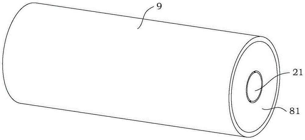
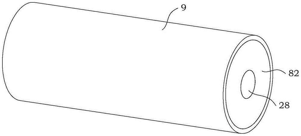
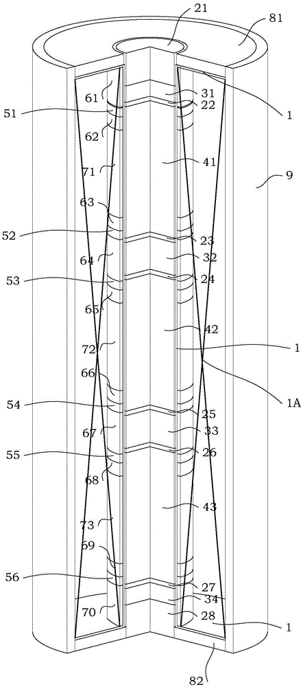
[0071]Ansys6.0 is used to simulate and measure the average magnetic field strength of the magnetostrictive rod: the central component is placed in the through hole of the coil cylinder, the intermediate component is sleeved on the coil cylinder, the enameled wire is wound on the intermediate component, and the magnetic permeable cylinder is 9 liang Install the first magnetic yoke 81 and the second magnetic yoke 82 on the end. The AA magnetic conduction column 21 in the center component is an active output terminal. The upper end of the permanent magnet column is an N pole, and the lower end is an S pole. The remanence of the permanent magnet column, permanent magnet ring and permanent magnet cylinder is 1.4 tesla.

[0072] (A) The magnetostrictive rod (AA magnetostrictive rod 41, AB magnetostrictive rod 42, AC magnetostrictive rod 43) has a diameter of 30 mm and a height of 60 mm.

[0073] (B) The diameter of the AB magnetically permeable column 22, the AC magnetically perme...

Embodiment 2

[0082] Ansys6.0 is used to simulate and measure the average magnetic field strength of the magnetostrictive rod: the central component is placed in the through hole of the coil cylinder, the intermediate component is sleeved on the coil cylinder, the enameled wire is wound on the intermediate component, and the magnetic permeable cylinder is 9 liang Install the first magnetic yoke 81 and the second magnetic yoke 82 on the end. The AA magnetic conduction column 21 in the center component is an active output terminal. The upper end of the permanent magnet column is an N pole, and the lower end is an S pole. The residual magnetism of the permanent magnet column, permanent magnet ring and permanent magnet cylinder is 1.0 Tesla.

[0083] Under the same parameters as in Example 1, except that the height change of the permanent magnet ring is 4 mm, the height change of the permanent magnet cylinder is 20 mm, BB mounting ring 62, BC mounting ring 63, BE mounting ring 65, BF mounting ...

Embodiment 3

[0086] Ansys6.0 is used to simulate and measure the average magnetic field strength of the magnetostrictive rod: the central component is placed in the through hole of the coil cylinder, the intermediate component is sleeved on the coil cylinder, the enameled wire is wound on the intermediate component, and the magnetic permeable cylinder is 9 liang Install the first magnetic yoke 81 and the second magnetic yoke 82 on the end. The AA magnetic conduction column 21 in the center component is an active output terminal. The upper end of the permanent magnet column is an N pole, and the lower end is an S pole. The remanence of the permanent magnet column, permanent magnet ring and permanent magnet cylinder is 0.4 Tesla.

[0087] Under the same parameters as in Example 1, except that the height change of the permanent magnet ring is 2 mm, the height change of the permanent magnet cylinder is 14 mm, BB mounting ring 62, BC mounting ring 63, BE mounting ring 65, and BF mounting ring ...


PUM

PropertyMeasurementUnit
diameteraaaaaaaaaa
diameteraaaaaaaaaa
diameteraaaaaaaaaa

Abstract

The invention discloses a permanent magnet biased magnetic circuit applicable to a giant magnetostrictive actuator. A central assembly of the permanent magnet biased magnetic circuit is arranged in a through hole of a coil framework. A pillar body of the coil framework is connected with a middle assembly in a sleeved mode, and the middle assembly is wound with varnished wires to form a coil. A magnetic cylinder is arranged outside the permanent magnet biased magnetic circuit, and the two ends of the magnetic cylinder are provided with magnetic yokes. Magnetostrictive rods, permanent magnetic columns, magnetic columns, the magnetic yokes and the magnetic cylinder form a biased magnetic field magnetism-supplying magnetic circuit. The two ends of each magnetostrictive rod are provided with the magnetic columns. The permanent magnetic columns are arranged outside the magnetic columns to form a biased magnetic field-actuating unit. According to the permanent magnet biased magnetic circuit applicable to the giant magnetostrictive actuator, the permanent magnetic columns serve as the biased magnetic field sources of the actuator, and larger magnetic field strength is achieved in the magnetostrictive rods through fewer permanent magnetic materials. Through the mode that the central assembly is sleeved with the middle assembly, magnetic leakage of the biased magnetic field magnetism-supplying magnetic circuit is lowered, and biased magnetic fields which have certain strength and are even are provided for the magnetostrictive rods.

Description

technical field [0001] The invention relates to a permanent magnet bias magnetic circuit, more particularly, a permanent magnet bias magnetic circuit device that can provide high uniformity and high magnetic field strength and is suitable for giant magnetostrictive actuators. Background technique [0002] Giant magnetostrictive actuator is a kind of actuator that uses giant magnetostrictive material to generate strain under the action of alternating magnetic field to obtain displacement output. It has the characteristics of large displacement output, large force output, high energy conversion rate, and rapid response. It has great application potential in the fields of intelligent structures such as aerospace, electronic power, and information communication. [0003] Due to the magnetic field strain characteristic of the giant magnetostrictive material itself, it is usually necessary to provide a bias magnetic field in order to optimize its performance. The bias magnetic fi...

Claims


Application Information

Patent Timeline
Patent Type & Authority Patents(China)
IPC IPC(8): H02N2/00H01F7/00
Inventor 张天丽余金安夏庆张恒蒋成保徐惠彬
Owner BEIHANG UNIV
Why Eureka
Try Eureka