Expandable tip delivery system and method

a stent-graft and tip technology, applied in the field of medical devices and procedures, can solve the problems of high likelihood of asymmetrical deployment of stent-grafts, less than ideal placement of stent-grafts, general undesirable effects, etc., and achieve the effect of avoiding the need for additional stent-grafts

Active Publication Date: 2012-03-13
MEDTRONIC VASCULAR INC
View PDF8 Cites 42 Cited by
  • Summary
  • Abstract
  • Description
  • Claims
  • Application Information

AI Technical Summary

Benefits of technology

[0016]By centering the stent-graft prior to deployment with the expandable tip, the initial deployment of the stent-graft is substantially orthogonal to the axial centerline of the curved vessel at the deployment location. As the initial deployment of the stent-graft is symmetric, repositioning of the stent-graft after initial deployment is avoided. Accordingly, the stent-graft is accurately placed within the curved vessel and the need to deploy additional stent-grafts is avoided.

Problems solved by technology

However, in complex vessels, e.g., in the aortic arch or other curved vessel, placement of the stent-graft becomes less than ideal.
This positioning of the distal tip of the delivery system combined with the effect of blood flow as the stent-graft is deployed results in a high likelihood for asymmetrical deployment of the stent-graft.
To correct the initial asymmetrical deployment, the physician typically repositions the stent-graft, which is generally undesirable depending upon the particular application.

Method used


Image

  • Expandable tip delivery system and method
  • Expandable tip delivery system and method
  • Expandable tip delivery system and method

Examples


Embodiment Construction

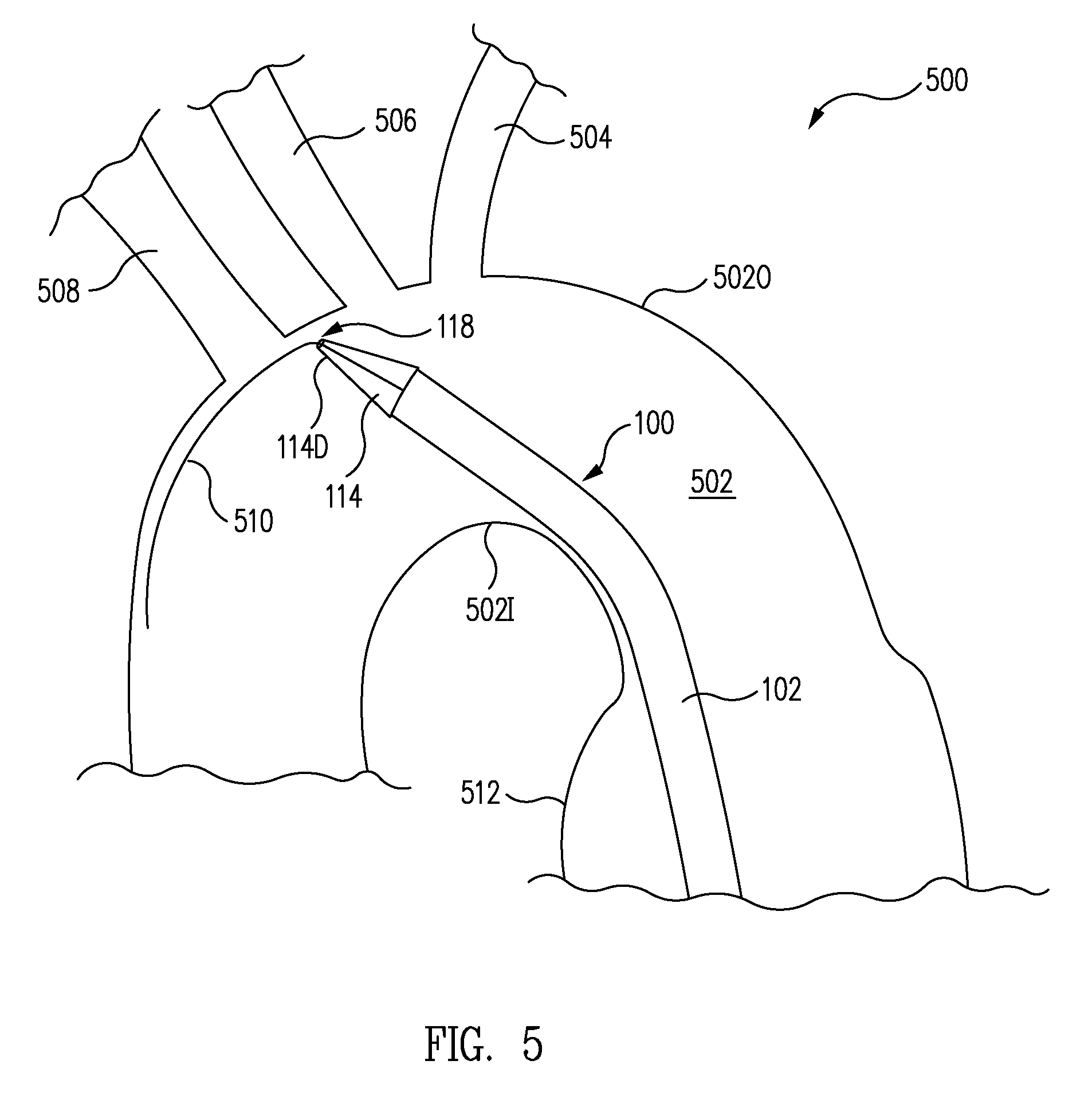
[0027]In accordance with one embodiment, referring to FIGS. 5, 6, 7, and 8 together, a method of deploying a stent-graft 106 in a curved vessel 502 with an expandable tip stent-graft delivery system 100 includes deploying an expandable tip 114 to center a distal end of the delivery catheter in curved vessel 502 as illustrating FIG. 6. A sheath 102 is retracted to expose stent-graft 106 as illustrated in FIG. 7, wherein stent-graft 106 self-expands into curved vessel 502. After deployment of stent-graft 106, expandable tip 114 is collapsed.

[0028]By centering the distal end of the delivery catheter prior to deployment with expandable tip 114, the initial deployment of stent-graft 106 is substantially orthogonal to the central longitudinal axis of the curved vessel 502. As the initial deployment of stent-graft 106 is symmetric, repositioning of stent-graft 106 sometime required when using prior art systems after initial deployment is avoided. Accordingly, there is a high likelihood tha...


PUM


Abstract

A method of deploying a stent-graft in a curved vessel includes deploying an expandable tip to center a proximal end of the catheter containing a stent-graft in the curved vessel. A sheath is retracted to expose the stent-graft and the stent-graft self-expands into the curved vessel. By centering the catheter containing the stent-graft prior to deployment with the expandable tip, the accuracy of stent graft placement within the curved vessel is improved.

Description

BACKGROUND OF THE INVENTION[0001]1. Field of the Invention[0002]This invention relates generally to medical devices and procedures, and more particularly to a method and system of deploying stent-grafts in a vascular system.[0003]2. Description of Related Art[0004]Prostheses for implantation in blood vessels or other similar organs of the living body are, in general, well known in the medical art. For example, prosthetic vascular grafts formed of biocompatible materials (e.g., Dacron or expanded, porous polytetrafluoroethylene (PTFE) tubing) have been employed to replace or bypass damaged or occluded natural blood vessels.[0005]A graft material supported by a framework is known as a stent-graft or endoluminal graft. In general, the use of stent-grafts for treatment or isolation of vascular aneurysms and vessel walls which have been thinned or thickened by disease (endoluminal repair or exclusion) is well known.[0006]Many stent-grafts, are “self-expanding”, i.e., inserted into the va...

Claims


Application Information

Patent Timeline
Patent Type & Authority Patents(United States)
IPC IPC(8): A61F2/84
CPCA61F2/95A61F2/966A61M25/0074A61M25/04A61M2025/0681
Inventor THOMAS, RICHARDCHANG, JANELLETHOMAS, CHARLESO'LEARY, AIDANGRAY, DAVIDIFTEKHAR, ARIF
Owner MEDTRONIC VASCULAR INC
Why Eureka
Try Eureka