Nanomagnetic signal propagation and logic gates

a technology of logic gates and magnets, applied in the direction of magnets, magnets, cores/yokes, etc., can solve the problems of premature alignment of the magnetization direction, and achieve the effect of reducing the anisotropy of the shape and increasing the hard-axis stability of the nanomagn

Inactive Publication Date: 2012-03-13
RGT UNIV OF CALIFORNIA
View PDF12 Cites 0 Cited by
  • Summary
  • Abstract
  • Description
  • Claims
  • Application Information

AI Technical Summary

Benefits of technology

[0005]According to one embodiment of the present invention, hard-axis metastability is created by aligning an easy axis of a biaxial anisotropy characteristic with a hard axis of a uniaxial anisotropic characteristic. Proper axes alignment increases nanomagnet hard-axis metastability so that factors such as thermal fluctuations, lithographic inconsistencies, and the like are insufficient to cause the magnetization direction to prematurely align along the easy axis prior to perturbation by the adjacent signal-propagating nanomagnet.
[0006]According to another embodiment of the present invention, nanomagnets in a column propagate a signal as a function of magnetization direction. The nanomagnets are aligned along their easy axes and unidirectional stabilizer nanomagnets are positioned adjacent to the nanomagnets in the column to increase hard-axis stability of the nanomagnets. The unidirectional stabilizer nanomagnets retain their magnetization direction due to a relatively large magnetic dipole moment, a biaxial anisotropy characteristic, and a substantially square shape that reduces shape anisotropy. Since the magnetization direction of the unidirectional stabilizer nanomagnets is identical to the magnetization direction of the nanomagnets when in hard-axis alignment, the hard-axis stability of the nanomagnets in the column is enhanced.
[0007]According to yet another embodiment of the present invention, a unidirectional nanomagnet is formed by positioning a first biasing magnet adjacent to a first side of a nanomagnet and closer to a first end portion of the nanomagnet, and positioning a second biasing magnet adjacent to a second side of the nanomagnet and closer to a second end portion of the nanomagnet. The first and second biasing magnets bias the magnetization direction of the nanomagnet such that the magnetization direction is prevented from aligning in a particular direction along the easy axis. The unidirectional nanomagnet can be used to inhibit signal propagation along a column of nanomagnets as a function of the magnetization direction of a signal-propagating adjacent nanomagnet.
[0008]According to yet another embodiment of the present invention, nanomagnetic logic gates are formed using nanomagnets and unidirectional nanomagnets that eliminate race conditions of signals propagating along multiple signal paths. The nanomagnetic logic gates can be configured to perform digital logic operations such as AND, NAND, NOR, and OR operations.

Problems solved by technology

Proper axes alignment increases nanomagnet hard-axis metastability so that factors such as thermal fluctuations, lithographic inconsistencies, and the like are insufficient to cause the magnetization direction to prematurely align along the easy axis prior to perturbation by the adjacent signal-propagating nanomagnet.

Method used


Image

  • Nanomagnetic signal propagation and logic gates
  • Nanomagnetic signal propagation and logic gates
  • Nanomagnetic signal propagation and logic gates

Examples


Embodiment Construction

[0021]The embodiments set forth below represent the necessary information to enable those skilled in the art to practice the invention and illustrate the best mode of practicing the invention. Upon reading the following description in light of the accompanying drawing figures, those skilled in the art will understand the concepts of the invention and will recognize applications of these concepts not particularly addressed herein. It should be understood that these concepts and applications fall within the scope of the disclosure and the accompanying claims.

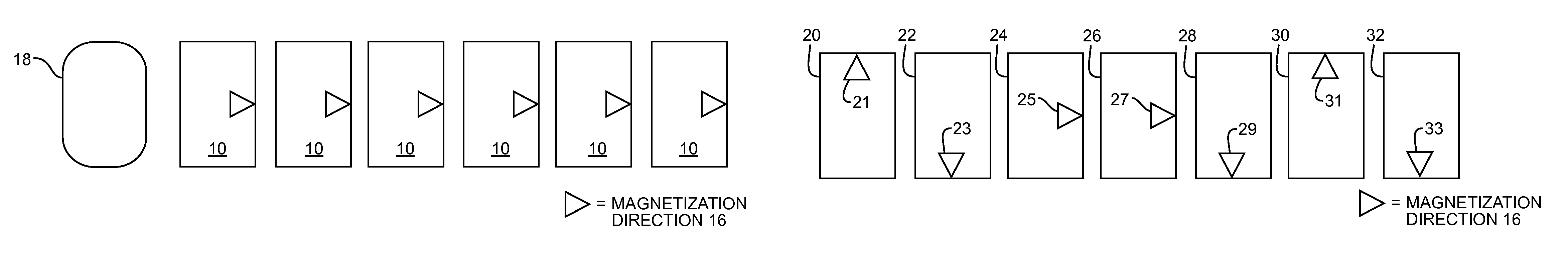
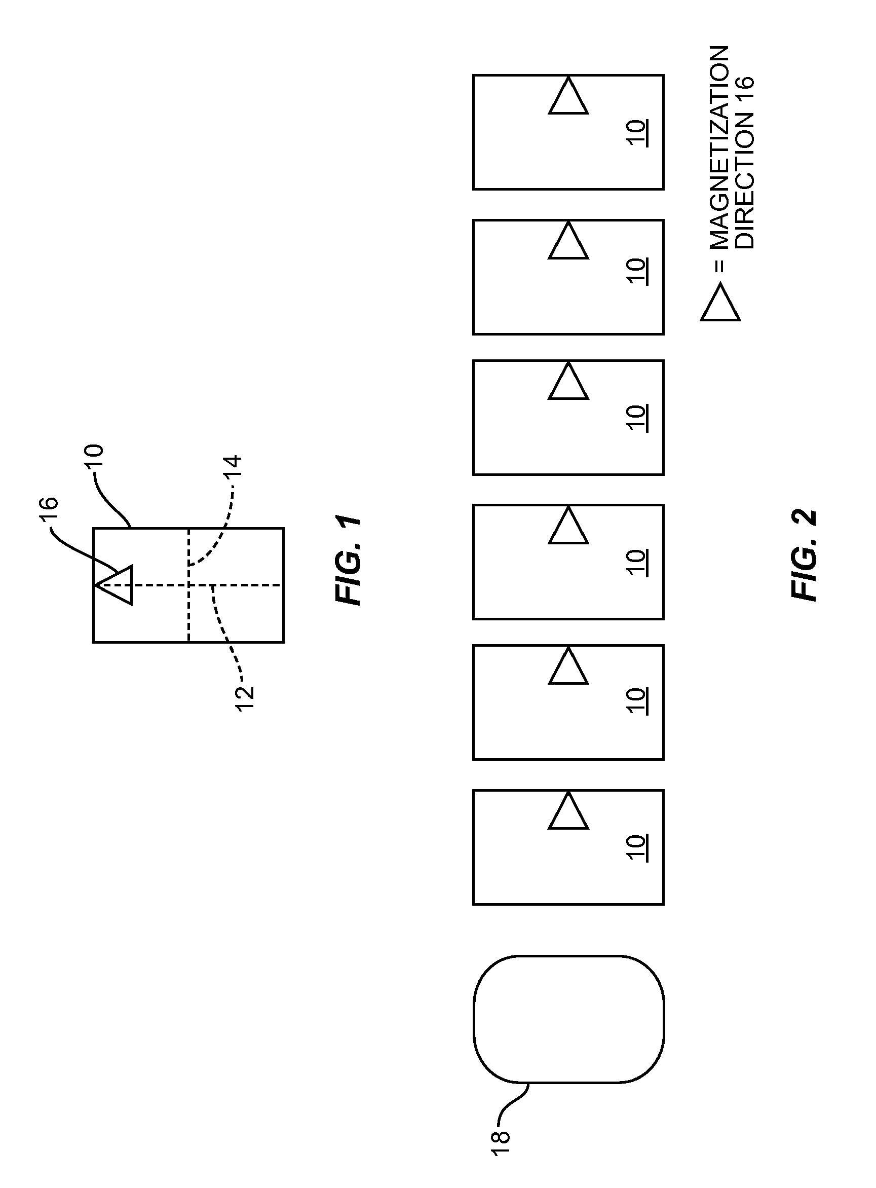
[0022]FIG. 1 shows a nanomagnet 10 having an easy axis 12, a hard axis 14, and a magnetization direction 16. A nanomagnet has a magnetic dipole defined by a dipole moment, which is a vector quantity having both a direction and a magnitude. As used herein, references to direction and / or magnetization direction refer to the direction component of the dipole moment associated with a respective nanomagnet. Generally, magnetic anisotro...


PUM

PropertyMeasurementUnit
thicknessaaaaaaaaaa
thicknessaaaaaaaaaa
thicknessaaaaaaaaaa

Abstract

A method and system for propagating signals along a line of nanomagnets. Nanomagnets having an easy axis and a hard axis are provided a biaxial anisotropy term, which increases metastability along the hard axis. The nanomagnets are forced into hard-axis alignment. A magnetization direction of a first nanomagnet is caused to cant upward. Dipole coupling interactions between the first nanomagnet and an adjacent nanomagnet cause a magnetization direction of the adjacent nanomagnet to cant downward in an anti-parallel alignment. This cascade continues reliably along the line of nanomagnets. The biaxial anisotropy term provides additional stability along the hard axis to ensure the nanomagnets do not prematurely align along the easy axis. Various logic gates using nanomagnets, stabilizer nanomagnets, destabilizer nanomagnets, and magnetic diodes are also disclosed.

Description

FIELD OF THE INVENTION[0001]This invention generally relates to nanomagnetic signal propagation, and in particular relates to increasing hard-axis metastability in nanomagnets.BACKGROUND OF THE INVENTION[0002]There is interest in exploring the use of nanometer-scale magnets, or nanomagnets, in signal propagation. There has been some limited success in propagating a signal along a row of nanomagnets. A force is applied to a row of nanomagnets to cause the magnetization direction of each nanomagnet to align with its relatively unstable hard axis, and then the external magnetic field is removed. The magnetization direction of a first nanomagnet in the row of nanomagnets is perturbed to cause the magnetization direction of the first nanomagnet to align with its relatively stable easy axis. Magnetic dipole field coupling between adjacent nanomagnets ideally causes a cascade of anti-parallel alignment of magnetization directions along the row of nanomagnets. However, cascade success depen...

Claims


Application Information

Patent Timeline
Patent Type & Authority Patents(United States)
IPC IPC(8): H01F7/02H01F1/00
CPCB82Y25/00H01F7/0205H01F1/009Y10T29/49075
Inventor BOKOR, JEFFREYEMLEY, NATHAN C.CARLTON, DAVID
Owner RGT UNIV OF CALIFORNIA
Why Eureka
Try Eureka