Disk drive head gimbal assembly including a PZT micro-actuator with a pair of separate PZT elements

a head gimbal and micro-actuator technology, which is applied in the direction of data recording, magnetic recording, instruments, etc., can solve the problems of increasing the manufacture cost, increasing the manufacturing cost, and increasing the difficulty of quickly and accurately positioning the read/write head over the desired information tracks on the disk, so as to reduce the waste of pzt elements and reduce the manufacture cost

Active Publication Date: 2012-03-13
SAE MAGNETICS (HK) LTD
View PDF5 Cites 7 Cited by
  • Summary
  • Abstract
  • Description
  • Claims
  • Application Information

AI Technical Summary

Benefits of technology

[0014]Accordingly, an object of the present invention is to provide a PZT micro-actuator for a head gimbal assembly (HGA). The PZT micro-actuator avoids the problem of weak structure existing in the prior art, reduces waste of PZT elements during manufacturing and detecting process and could detect the defect of each PZT layer individually, thereby reducing manufacture cost.
[0015]Another object of the present invention is to provide a head gimbal assembly (HGA) with a PZT micro-actuator. The HGA avoids the problem of weak structure existing in the prior art, reduces waste of PZT elements during manufacturing and detecting process and could detect the defect of each PZT layer individually, thereby reducing manufacture cost and improving shock performance of a suspension.
[0016]Another object of the present invention is to provide an assembling method for a head gimbal assembly to reduce manufacture cost.

Problems solved by technology

As track density increases, it becomes more and more difficult to quickly and accurately position the read / write head over the desired information tracks on the disk.
Second, the two piece PZT elements which are integratedly connected with each other easily causes an increase of the manufacture cost.
For example, on the one hand, when it is detected that one PZT element is damaged and thus should be discarded while the other PZT element is in a sound condition, the sound PZT element has no choice but to be also discarded as the two piece PZT elements are combined together, thereby causing the increase of the manufacture cost. on the other hand, as mentioned above, the corresponding electrode layers of all the PZT layers in the present PZT element are connected correspondingly (for example, all the positive electrodes are connected together and all the negative electrodes are also connected together).
That is, all PZT layers are parallelly connected between one pair of electrode layers, thus it is unable to detect the defect of a single PZT layer.
In other words, when one PZT element is damaged, it is impossible to detect which PZT layer of the PZT element is damaged, thereby the whole PZT element has to be discarded.
Similarly, as the corresponding electrode layers of all PZT layers are connected correspondingly by sputtering as mentioned above, the manufacture process is complex, further causing a higher manufacture cost.
Another drawback existing in the conventional HGA 100 shown in FIGS. 3, 4 relates to electrical connection method and shock performances.
As the whole structure of gold trace soldering possesses an extremely poor shock performance, it is easy to split or break especially when outer vibration or shock event happens.
Hence the whole structure of the HGA 100 has a terribly poor shock performance.
Besides, the prior art has other drawbacks.
Moreover, the suspension deformation resulted from such weak structure will adversely cause the suspension or HGA dimple separation. FIGS. 6 and 7 respectively show a suspension deformation and a dimple separation.
In addition, as the slider 103 is partially mounted on the slider support 121 and the slider support 121 is coupled with the metal base 123 via traces of the flexure 122, the static attitude of the slider 103 such as PSA (pitch static attitude) or RSA (roll static attitude) is unstable and difficult to control, which causes the HGA performance unstable and accordingly, affects the HGA dynamic performance seriously, especially when a vibration or shock event happens or during the manufacture process or handle process.
Finally, such structure makes the whole HGA a poor shock performance.

Method used


Image

  • Disk drive head gimbal assembly including a PZT micro-actuator with a pair of separate PZT elements
  • Disk drive head gimbal assembly including a PZT micro-actuator with a pair of separate PZT elements
  • Disk drive head gimbal assembly including a PZT micro-actuator with a pair of separate PZT elements

Examples


Embodiment Construction

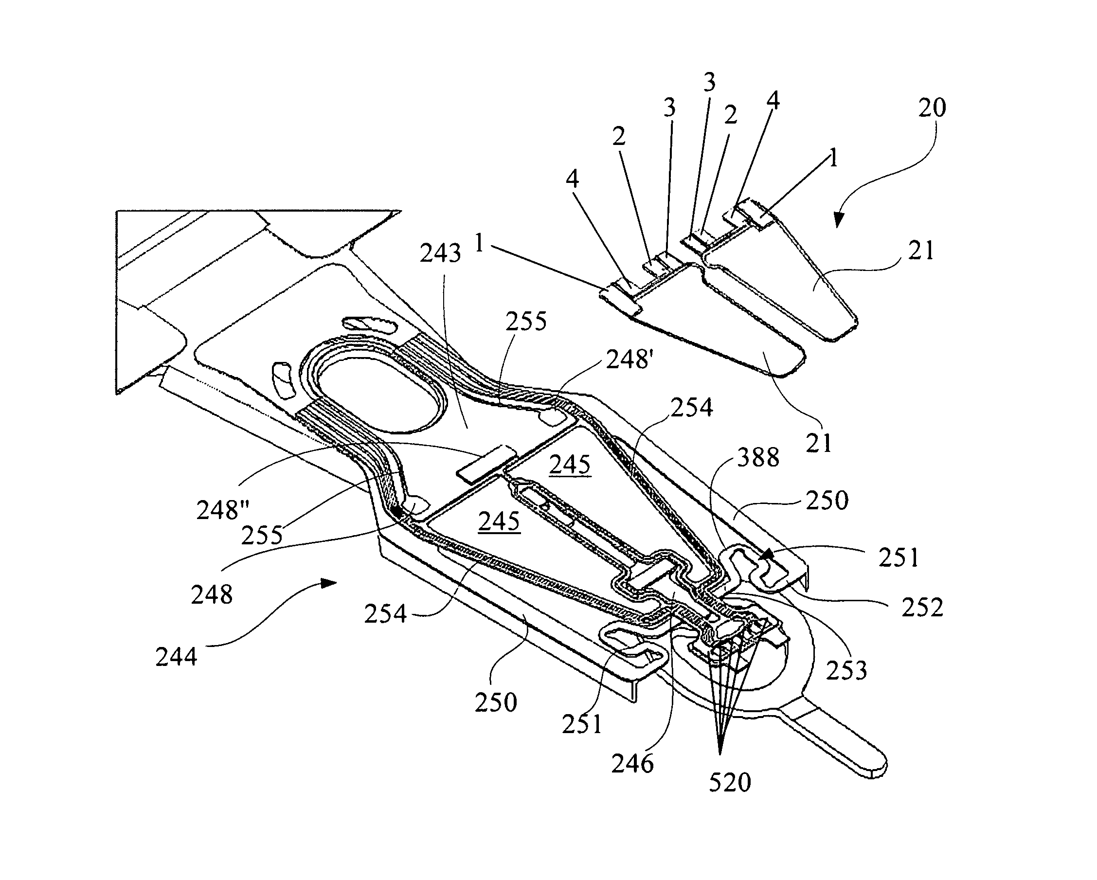
[0054]Various preferred embodiments of the invention will now be described with reference to the figures, wherein like reference numerals designate similar parts throughout the various views. An embodiment of a PZT micro-actuator for a head gimbal assembly is first illustrated. FIGS. 8a-8d illustrate the embodiment of a PZT micro-actuator according to the present invention. As shown in FIG. 8a, compared with conventional PZT micro-actuator formed by two piece PZT elements connected together, the present invention provides a PZT micro-actuator 20 formed by two piece PZT elements 21 separate from each other.

[0055]Each PZT element 21 has a sheet-shaped body 29 and a plurality of, such as four electrical pads 1, 2, 3 and 4 formed on the sheet-shaped body 29. FIG. 8b illustrates the detailed structure of the PZT element 21. As shown in FIG. 8b, the body 29 comprises multiple PZT layers such as the first PZT layer 22 and the second PZT layer 23 laminated together. In addition, each PZT la...


PUM

PropertyMeasurementUnit
thicknessaaaaaaaaaa
distanceaaaaaaaaaa
distanceaaaaaaaaaa

Abstract

A PZT micro-actuator for a head gimbal assembly includes a pair of separate PZT elements and each PZT element has a body and a plurality of electrical pads. The body has at least two electrode-piezoelectric combination layers laminated together. The at least two electrode-piezoelectric combination layers are physically connected with but electrically isolated from each other. Each electrode-piezoelectric combination layer has at least two of the electrical pads thereon. The electrical pads extend out from the body of the corresponding PZT element. All the electrical pads of each PZT element are offset a predetermined distance therebetween to be electrically isolated. The present invention also discloses a head gimbal assembly (HGA) with the PZT micro-actuator, an assembling method for the head gimbal assembly and a disk drive unit having such HGA.

Description

[0001]This application claims priority to Chinese Application No. 200810080407.4 filed Feb. 2, 2008, the entire contents of which are hereby incorporated by reference.FIELD OF THE INVENTION[0002]The present invention relates to an information recording disk drive device, and more particularly, to a piezoelectric (PZT) micro-actuator, a head gimbal assembly (HGA) with the PZT micro-actuator, an assembling method for the HGA, and a disk drive device with the HGA.BACKGROUND OF THE INVENTION[0003]Disk drives are information storage devices that use magnetic media to store data and a movable read / write head positioned over the magnetic media to selectively read data from and write data to the magnetic media.[0004]Consumers are constantly desiring greater storage capacity for such disk drive devices, as well as faster and more accurate reading and writing operations. Thus, disk drive manufacturers have continued to develop higher capacity disk drives by, for example, increasing the record...

Claims


Application Information

Patent Timeline
Patent Type & Authority Patents(United States)
IPC IPC(8): G11B5/56G11B21/24
CPCG11B5/4826G11B5/4873G11B5/5552G11B5/483
Inventor YAO, MINGGAOGUO, LINSUN, YU
Owner SAE MAGNETICS (HK) LTD
Why Eureka
Try Eureka