Operating method of electrical pulse voltage for RRAM application

a technology of electrical pulse voltage and rram, which is applied in the field of metal-oxide-based memory devices, can solve the problems of increasing the complexity of the circuitry of memory devices employing these types of metal-oxide materials, increasing the test time of the device, and dc voltage taking a relatively large time, so as to achieve the effect of increasing the initial resistance of the metal-oxide material

Active Publication Date: 2012-03-13
MACRONIX INT CO LTD
View PDF10 Cites 7 Cited by
  • Summary
  • Abstract
  • Description
  • Claims
  • Application Information

AI Technical Summary

Benefits of technology

[0013]A method for manufacturing a memory device as described herein comprises forming a metal-oxide memory element, and applying an activating energy to the metal-oxide memory element. In embodiments the activating energy can be applied by applying electrical and / or thermal energy to the metal-oxide material. Unlike the forming process of FIG. 1 in which high resistance material is formed to a lower resistance state in order to enable the resistive switching behavior, the activating energy described herein can remove leakage paths inside the metal-oxide material and result in an increase in the initial resistance of the metal-oxide material.
[0015]Applying the activating energy as described herein is shown to result in the ability to use lower operating voltages for programming the metal-oxide memory element 140. Thus, the electrical stress on the memory element can be reduced and improved cycle endurance is observed. Additionally, applying the activating energy is shown to improve read disturbance and result in a larger resistance window between the resistance states, thereby providing an opportunity for multi-bit operation.

Problems solved by technology

The relatively large forming voltage (Vforming) increases the complexity of the circuitry of memory devices employing these types of metal-oxide materials.
Additionally, the forming process of sweeping the DC voltage takes a relatively large time (for example greater than 60 μs), which increases the test time of the device significantly.
However, endurance problems have arisen using large magnitude reset pulses due to instability of the resistance of the metal-oxide material, resulting in reliability issues and possible failure of the device.

Method used


Image

  • Operating method of electrical pulse voltage for RRAM application
  • Operating method of electrical pulse voltage for RRAM application
  • Operating method of electrical pulse voltage for RRAM application

Examples


Embodiment Construction

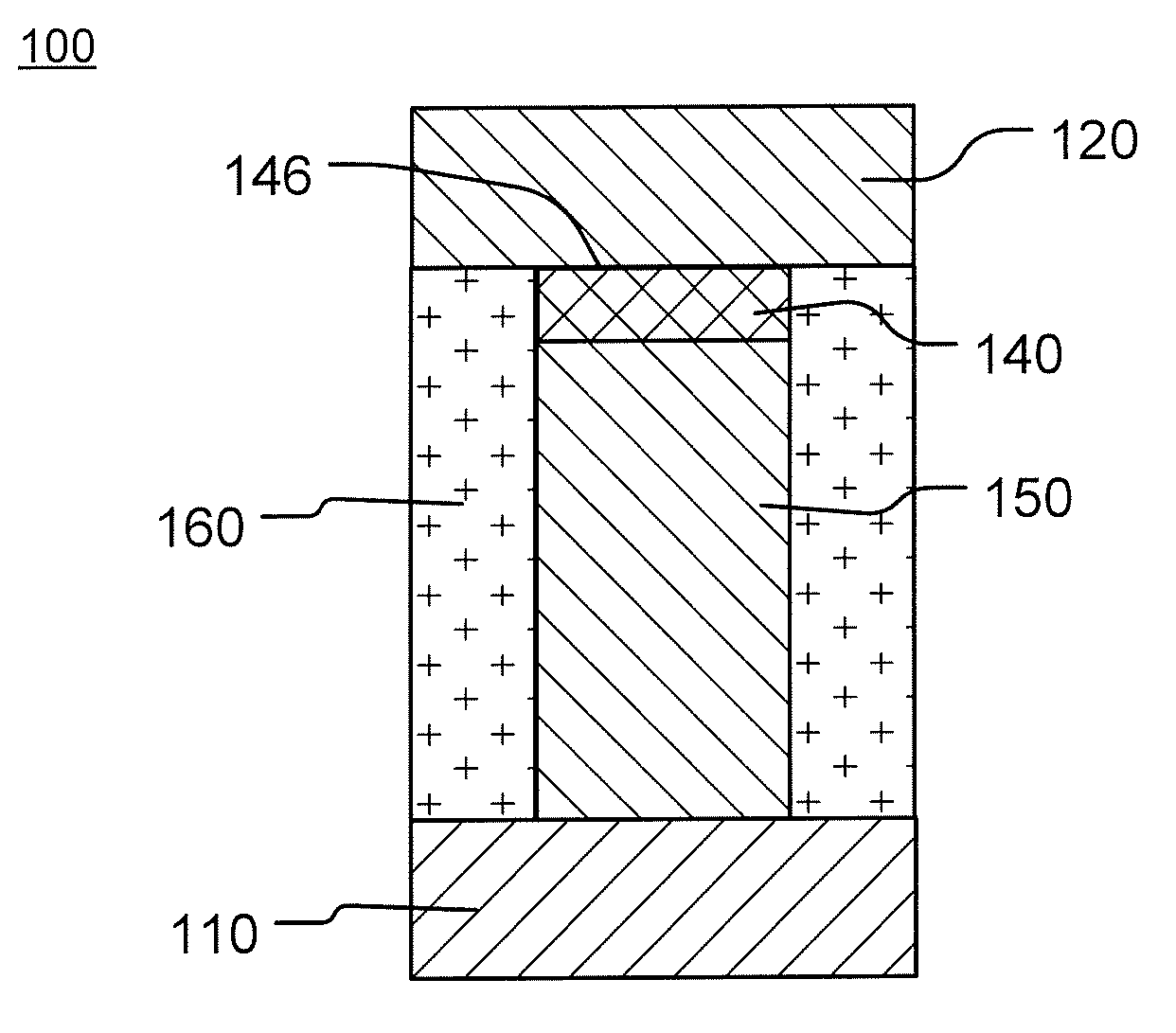
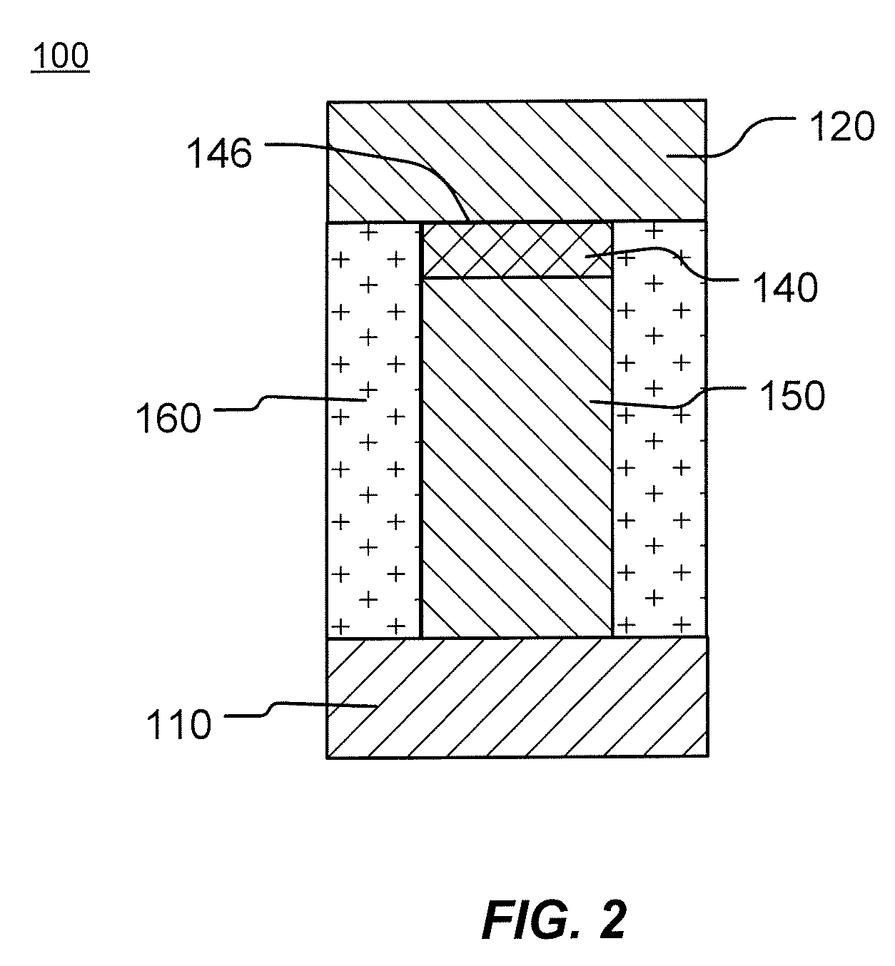
[0034]The following description of the disclosure will typically be with reference to specific structural embodiments and methods. It is to be understood that there is no intention to limit the disclosure to the specifically disclosed embodiments and methods, but that the disclosure may be practiced using other features, elements, methods and embodiments. Preferred embodiments are described to illustrate the present disclosure, not to limit its scope, which is defined by the claims. Those of ordinary skill in the art will recognize a variety of equivalent variations on the description that follows. Like elements in various embodiments are commonly referred to with like reference numerals.

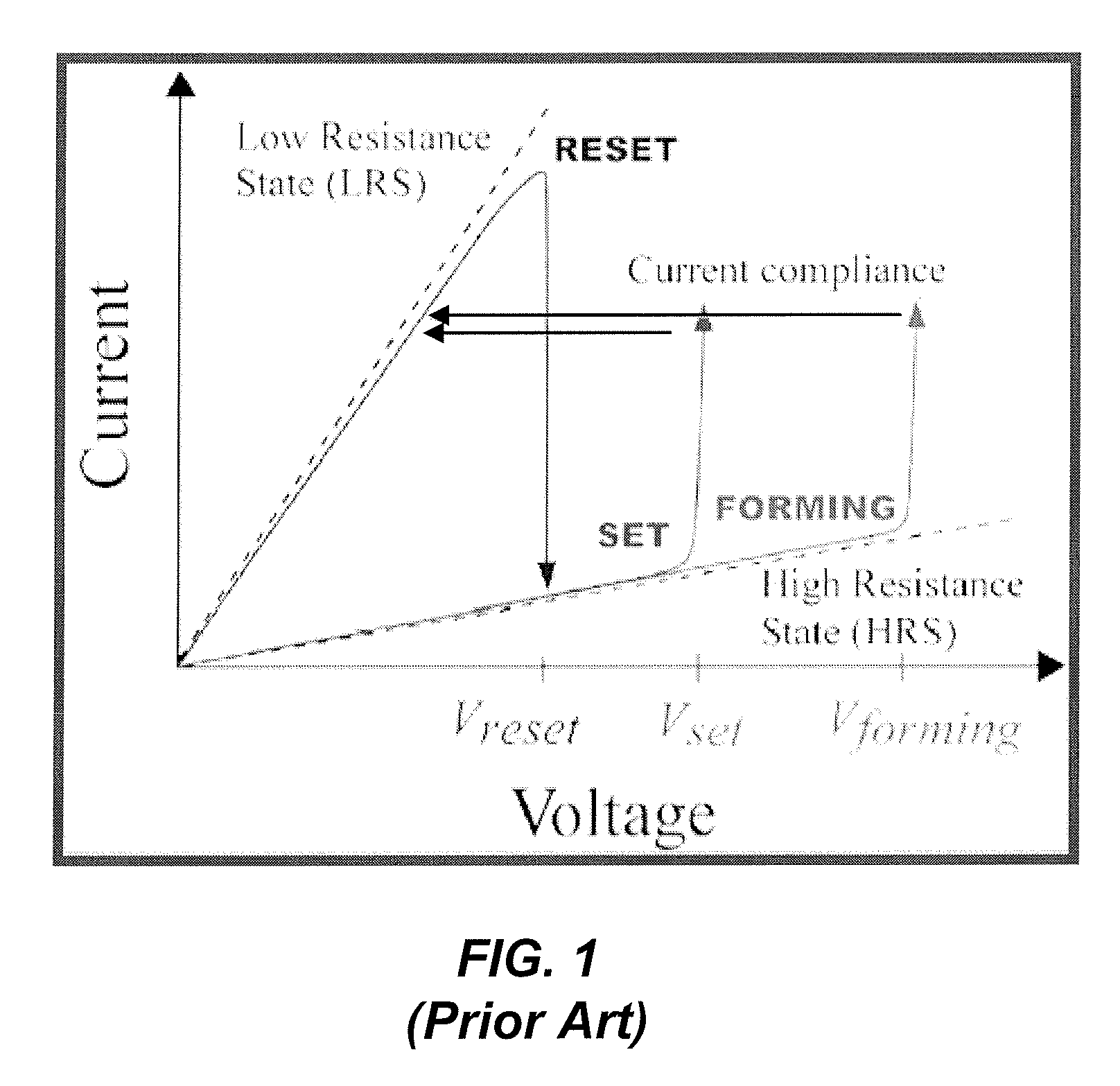
[0035]As described above, endurance problems have arisen using large magnitude pulses to change to the highest resistance state due to instability in the resistance of metal-oxide memory elements which reduce the resistance window between the highest and lowest resistance state, resulting in reliabi...


PUM


Abstract

Metal-oxide based memory devices and methods for operating and manufacturing such devices are described herein. A method for manufacturing a memory device as described herein comprises forming a metal-oxide memory element, and applying an activating energy to the metal-oxide memory element. In embodiments the activating energy can be applied by applying electrical and / or thermal energy to the metal-oxide material.

Description

CROSS-REFERENCE TO RELATED APPLICATIONS[0001]This application claims the benefit of U.S. Provisional Patent Application No. 61 / 050,774 titled “Operation Method of Electrical Pulse Voltage for RRAM Application” filed on 6 May 2008, which is incorporated by reference herein.BACKGROUND OF THE INVENTION[0002]1. Field of the Invention[0003]The present invention relates to metal-oxide based memory devices and methods for operating and manufacturing such devices.[0004]2. Description of Related Art[0005]Some metal-oxides can be caused to change resistance between two or more stable resistance ranges by application of electrical pulses at levels suitable for implementation in integrated circuits, thus providing a basis for use in nonvolatile resistive random access memory RRAM. Metal-oxide based RRAM has attracted much attention because of its simple structure, high speed, low power consumption, and compatibility with standard CMOS processes.[0006]In metal-oxide based memory, data is stored ...

Claims


Application Information

Patent Timeline
Patent Type & Authority Patents(United States)
IPC IPC(8): G11C11/00
CPCC07D413/14G11C13/0007G11C13/0069H01L45/04H01L45/1233H01L45/146H01L45/1633H01L45/1641C07D413/04C07D417/14C07D417/04G11C11/5685G11C7/20G11C2013/0083G11C2013/009G11C2213/32G11C2213/34G11C2213/79H01L27/2436H10B63/30H10N70/20H10N70/028H10N70/041H10N70/8833H10N70/826
Inventor CHANG, KUO-PINCHEN, YI-CHOUCHIEN, WEI-CHIHLAI, ERH-KUN
Owner MACRONIX INT CO LTD
Why Eureka
Try Eureka