Method of launching into operational orbit an artificial satellite and associated propulsion device

Active Publication Date: 2012-03-20
ASTRIUM SAS
View PDF20 Cites 11 Cited by
  • Summary
  • Abstract
  • Description
  • Claims
  • Application Information

AI Technical Summary

Benefits of technology

[0016]The commercial constraint of the compatibility of satellites with such launchers therefore leads to the development of another method allowing a satellite to be placed in geostationary orbit from a transfer orbit, without however losing the advantages brought by a direct launch into geostationary orbit by the launcher, one of the most important of which is that the fuel saved on the satellite through direct launching into geostationary orbit frees up space in the satellite, so that the payload taken onboard can be increased, thus reducing the operating costs very significantly, ensuring greater competitiveness. This commercial constraint of compatibility of the satellites with several types of launcher also applies to orbits other than geostationary orbits, for example intermediate circular orbits, known as MEOS, such as those used by navigation constellation satellites (GPS or Galileo).
[0023]This method has the advantage that the satellite's own propulsion system only needs to consume a small quantity of propellants to move from the intermediate orbit to the operational orbit, and that there is no need to reignite the thruster(s) of the propulsion device on the one hand and of the last stage of the launcher on the other hand, to convey them respectively to a graveyard orbit, as the propulsion device and the last stage of the launcher can remain respectively in the intermediate orbit and the transfer orbit.
[0045]In this case, for reasons of balance, the two toroidal tanks are advantageously slanted relative to each other in opposite phase, that is, such that the highest point of one corresponds to the lowest point of the other, and vice versa. For physico-chemical reasons, because the melting points of the two propellants are generally different from each other, it is preferable that the said at least one toroidal tank inside the adapter is intended to contain whichever of the fuel and oxidizer propellants has the highest melting point, so that this propellant receives better thermal protection from the sidereal vacuum. This measure saves energy by saving on the operation of a heating system equipping the propellant tank. Furthermore, the toroidal geometry of the propellant tanks lends itself well to the placing, inside a standard conical interface adapter (the large and small bases of which are intended to be separably attached to the launcher and the satellite respectively), of an additional tank, preferably spherical, which is the pressurisation tank containing helium to pressurise the propellant tanks to a sufficient pressure for the expulsion of the propellants into the manifold circuits linking the tanks to the apogee thruster, and allowing for the mixing of the fuel and oxidizer on entry to the thruster, the installation of which inside the adapter is also facilitated by the toroidal geometry of the propellant tanks.

Problems solved by technology

However, this direct geostationary orbit injection method poses a number of problems.
Moreover, if the upper stage of the launcher encounters a major problem in the orbit close to the geostationary orbit, the launcher upper stage can remain locked in that orbit or even explode and thus create debris dangerous to the geostationary satellites.
However, this method nevertheless has the drawback of requiring the use of a more powerful launcher than those allowing for launches into geostationary orbit by the more conventional method comprising a first stage of injection of the satellite into a transfer orbit followed by a second stage during which the satellite reaches the geostationary orbit by means of its own propulsion system.

Method used


Image

  • Method of launching into operational orbit an artificial satellite and associated propulsion device
  • Method of launching into operational orbit an artificial satellite and associated propulsion device
  • Method of launching into operational orbit an artificial satellite and associated propulsion device

Examples


Embodiment Construction

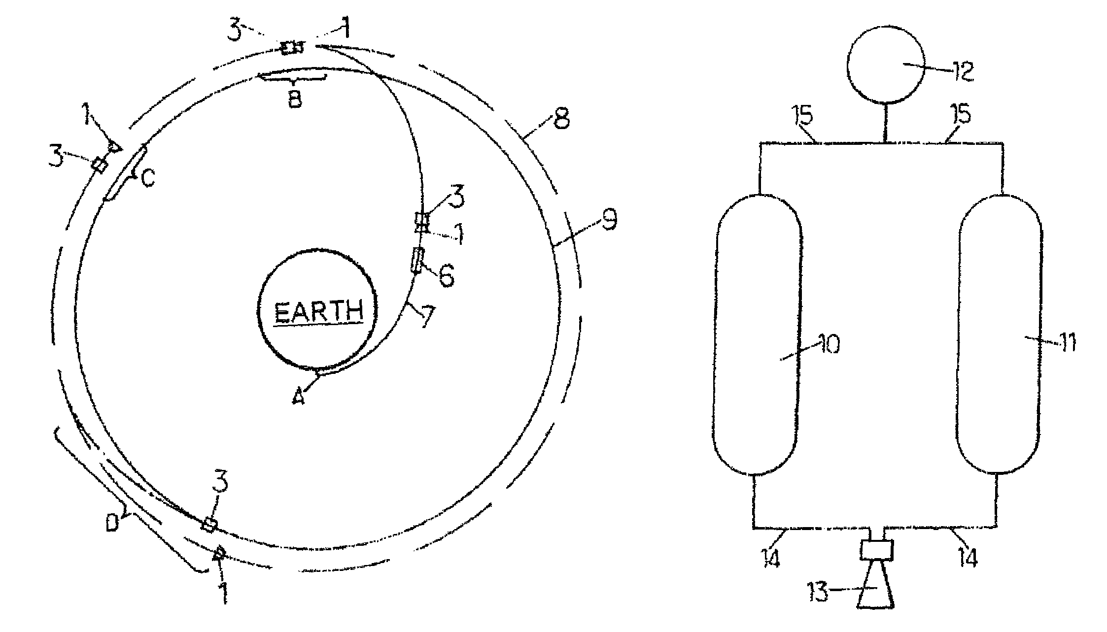
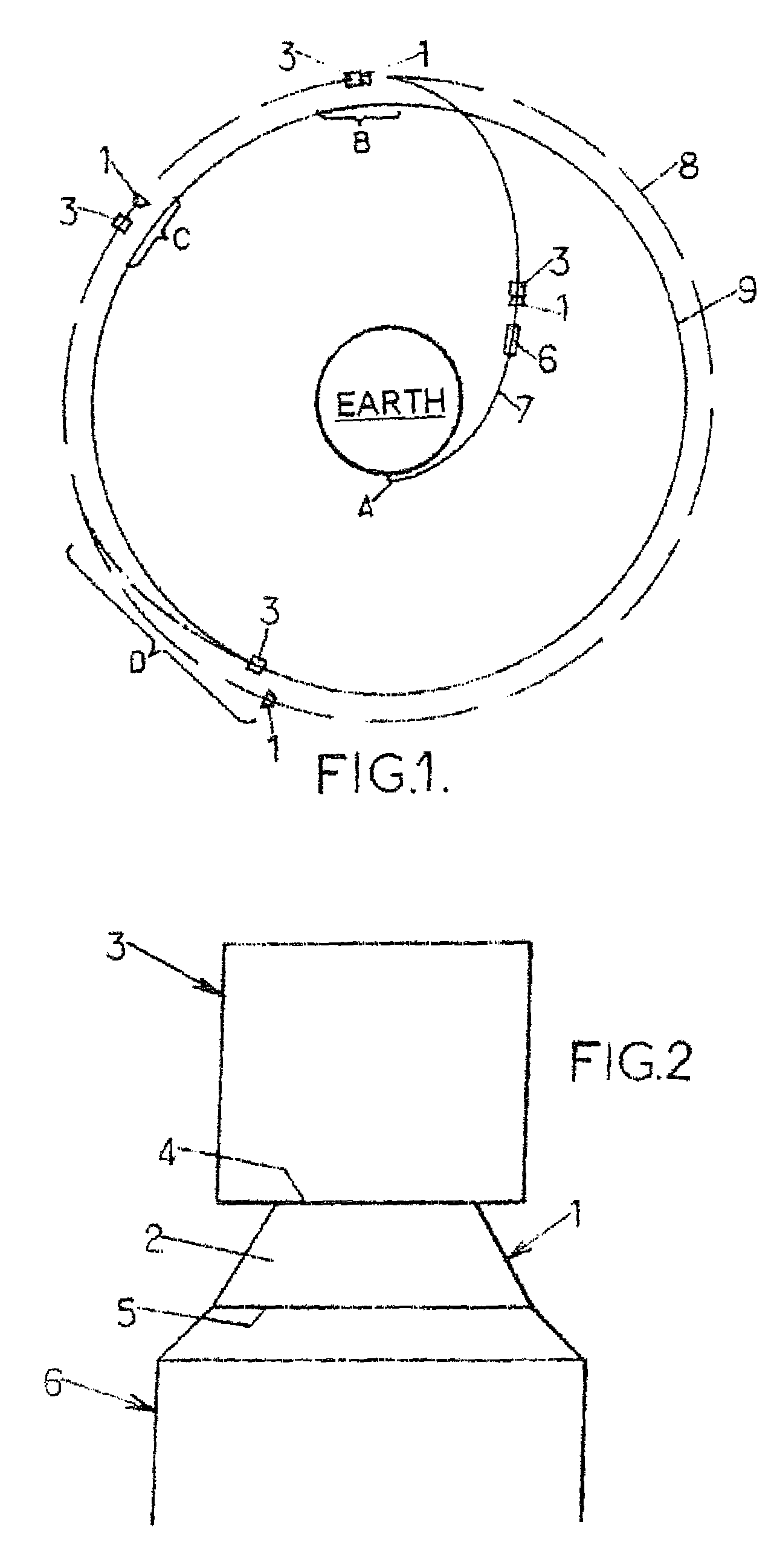
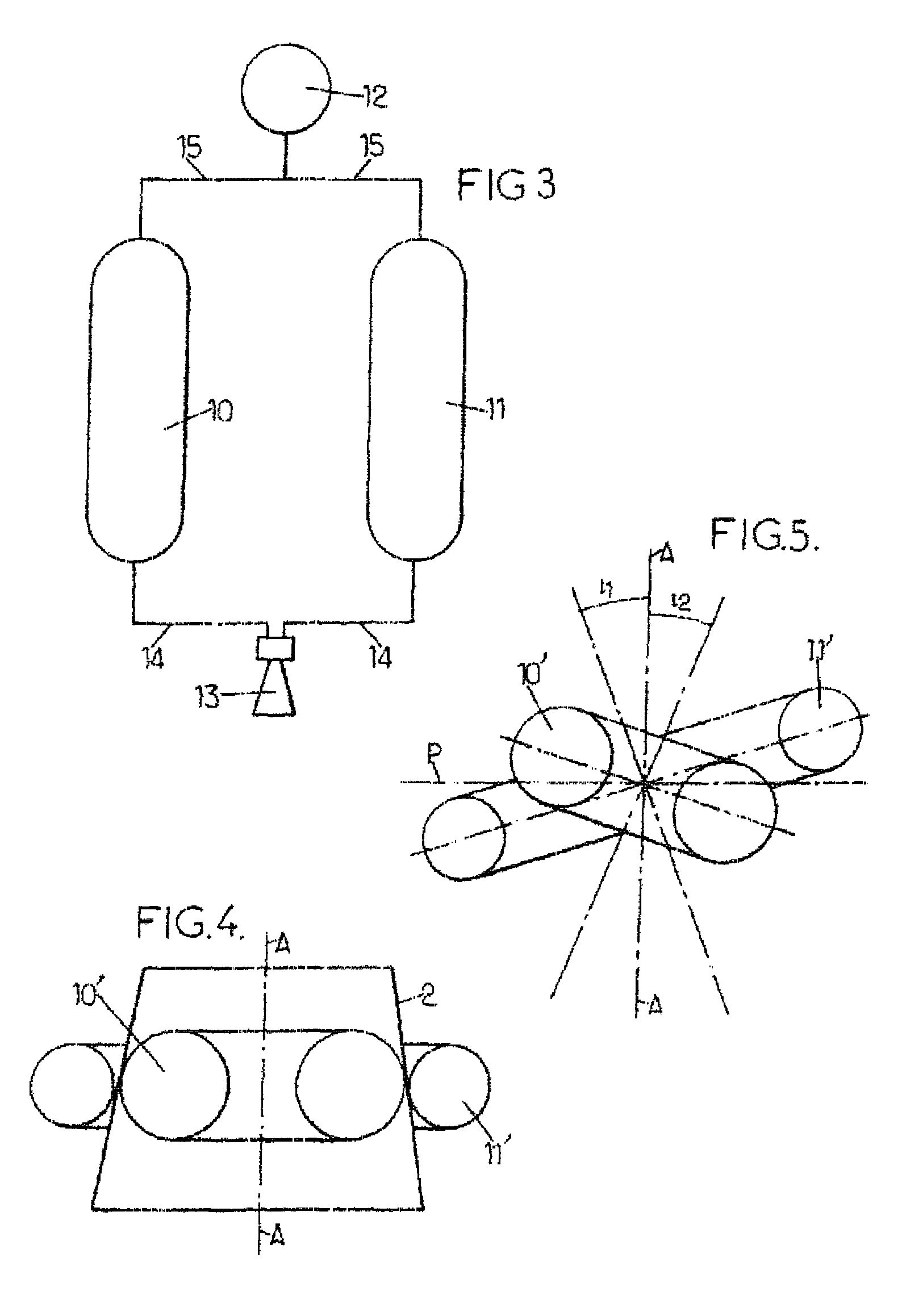
[0052]After the production of a propulsion device 1, arranged as a jettisonable auxiliary propulsion stage of the satellite 3 and controlled by it, through the arrangement of a conical interface adapter 2, as described below with reference to FIGS. 3 to 5, the satellite 3, equipped with its own propulsion system, is separably fixed, by a releasable coupling mechanism, to the small basis 4 (in the upper position) of the adapter 2, itself separably fixed, by its large basis 5, by another releasable coupling, to the upper end of the last stage (or upper stage) of a space launcher 6.

[0053]At the end of the first propelled phase carried out by the launcher 6, at point A in FIG. 1, the separation occurs, at the large basis 5 of the adapter 2, of the assembly made up of the satellite 3 and the propulsion device 1, on the one hand, and the upper stage of the launcher 6, on the other hand, after the injection by the launcher 6 of the satellite 3-propulsion device 1 assembly into an elliptica...


PUM


Abstract

A method is disclosed for placing a satellite in an operational orbit. The satellite is equipped with its own satellite propulsion system as well as a detachable separate propulsion device. The satellite and separate propulsion device are launched into a transfer orbit by means of a space launcher. The separate propulsion device is controlled by a satellite. The satellite is transferred from the transfer orbit to an intermediate orbit by means of the separate propulsion device. The separate propulsion device is separated from the satellite in the intermediate orbit. The satellite then enters and operational orbit from the intermediate orbit by means of its own satellite propulsion system. The intermediate orbit is disposed between the transfer and operational orbits, and is in relatively close proximity to the operational orbit but is far enough away from the operational orbit to prevent possible interferences.

Description

CROSS-REFERENCE TO RELATED APPLICATIONS[0001]This application is a U.S. national stage filing of International Patent Application No PCT / FR2007 / 051516 filed on Jun. 26, 2007, which claims priority under the Paris Convention to French Patent Application No 06 05794, filed on Jun. 27, 2006.FIELD OF THE DISCLOSURE[0002]This disclosure relates to a method of launching into operational orbit, and in particular geostationary orbit, an artificial satellite equipped with its own propulsion system, and this disclosure also relates to a propulsion device associated with the satellite for the launching into operational orbit of such satellite from a transfer orbit obtained by means of a space launcher.BACKGROUND OF THE DISCLOSURE[0003]The most common method of launching a satellite into geostationary orbit comprises a first stage, which is a stage of injection into a transfer orbit by a space launcher, followed, after separation of the launcher and the satellite, by a second stage, during whic...

Claims


Application Information

Patent Timeline
IPC IPC(8): B64G1/26
CPCB64G1/007B64G1/242B64G1/641B64G1/002B64G1/401B64G1/402B64G1/2427
Inventor GENESTE, JEAN-FRANCOISPOUSSIN, JEAN-FRANCOIS
Owner ASTRIUM SAS
Why Eureka
Try Eureka