Power converting circuit and controller thereof

a technology of power conversion circuit and controller, which is applied in the direction of electric variable regulation, process and machine control, instruments, etc., can solve the problems of low conversion efficiency of the controller, failure of the controller con operation, and inability to supply electric power, so as to shorten the life of the controller and ensure the safety of users

Active Publication Date: 2012-03-20
GREEN SOLUTION TECH CO LTD
View PDF3 Cites 8 Cited by
  • Summary
  • Abstract
  • Description
  • Claims
  • Application Information

AI Technical Summary

Benefits of technology

[0010]Accordingly, in an embodiment of the present invention, a controller is latched while an abnormal event occurs in a power converting circuit, so that the controller thereof stops providing a part or all of its functions until an input voltage is removed. As a result, the issues, such as shortened life-span and safety of users, due to the converting circuit in the related arts are avoided in an embodiment of the present invention.
[0011]One embodiment of the present invention provides a controller that is adapted to receive electric power required for operating through a driving voltage terminal and configured to control a converting circuit to convert an input voltage into an output voltage. The controller includes a start unit, a control unit, and a latch unit. The start unit is coupled to the driving voltage terminal and generates a starting signal after a driving voltage of the driving voltage terminal is higher than a first predetermined voltage. The control unit is started to control the converting circuit after receiving the starting signal. The latch unit is coupled to the driving voltage terminal and started after receiving the starting signal. Once the controller enters a protection mode, the latch unit generates a latch signal. After receiving the latch signal, the control unit terminates at least a portion of operation thereof to reduce the electric power required for operating, so that the driving voltage is maintained to be higher than a second predetermined voltage, wherein the second predetermined voltage is a lowest operating voltage of the latch unit, and the second predetermined voltage is lower than the first predetermined voltage.

Problems solved by technology

However, electric devices in the circuit are large, so that volume of the circuit is large, weight thereof is heavy, and further, conversion efficiency thereof is low.
Accordingly, the initial resistor R having a relatively large resistance is used to lower power consumption by the initial resistor R. However, when an abnormal event occurs in the circuit, the DC input voltage VIN can not supply the electric power to the AC output voltage VOUT, so that the transformer T2 and the diode D can not supply the electric power.
Moreover, the electric power transmitted through the initial resistor R is not enough to hold all of the electric power required by the controller CON while normally operating, so that the operation of the controller CON may fail.
As a result, the driving voltage VDD may start to fall down.
When the driving voltage VDD has become lower than a voltage range which the controller CON can tolerate, the controller CON stops operating and further consuming power.
In the process, not only life-span of the lamp is shortened due to limitation of start cycles thereof, but also users may get an electric shock while lamp replacing since the users forget to turn off the power source.
Accordingly, since the lamp driving circuit may re-start the lamp in the SPS of the related art, not only the life-span of the lamp is shortened, but also using it may be dangerous to the users.

Method used


Image

  • Power converting circuit and controller thereof
  • Power converting circuit and controller thereof
  • Power converting circuit and controller thereof

Examples


first embodiment

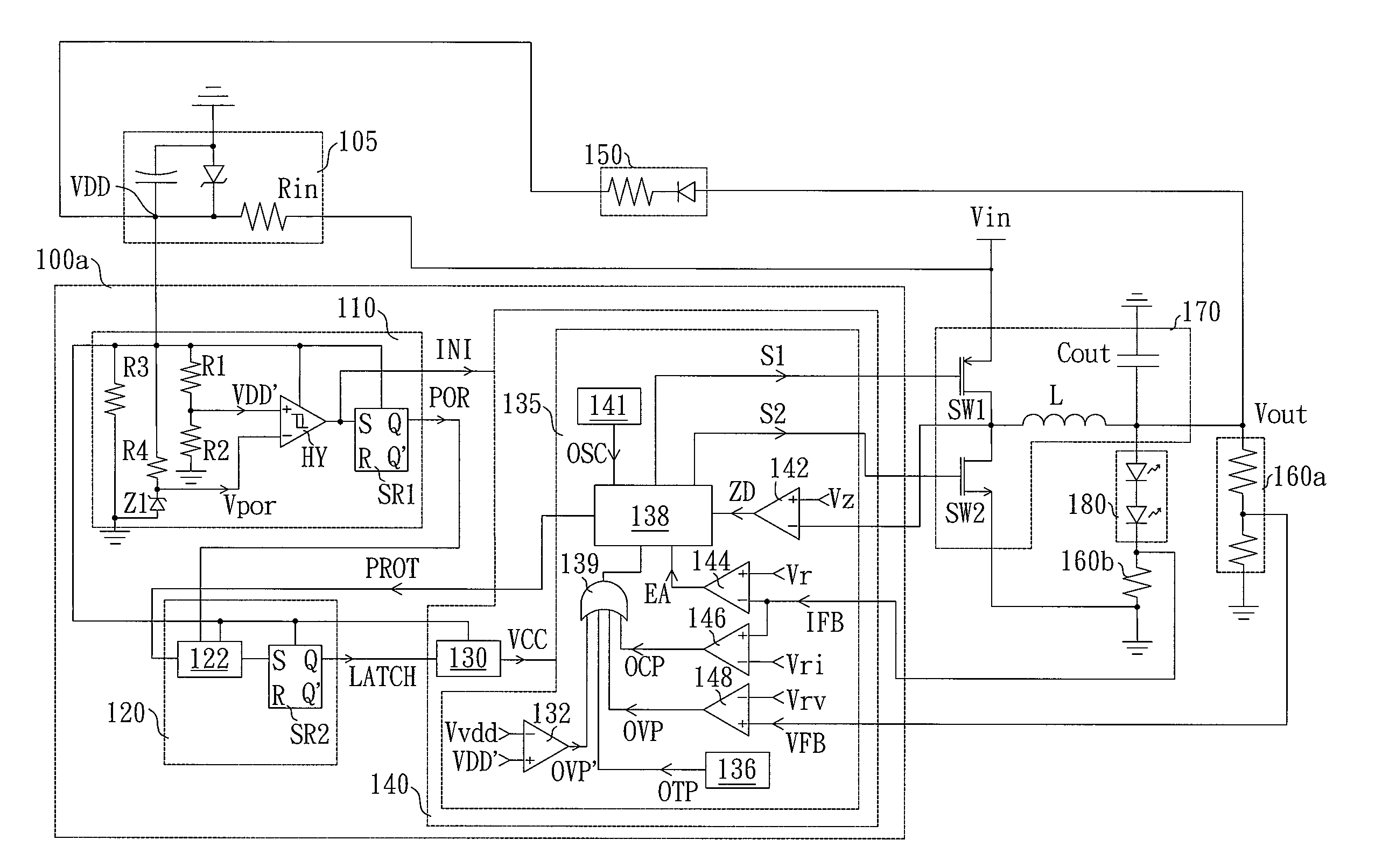
[0028]FIG. 4 is a schematic circuit of a power converting circuit consistent with the present invention. Referring to FIG. 4, the power converting circuit includes a controller 100a, a start circuit 105, a feedback circuit, a converting circuit 170, wherein the feedback circuit includes a first feedback unit 160a and a second feedback unit 160b. The power converting circuit converts an input voltage Vin to an output voltage Vout to drive a light-emitting diode (LED) module 180. The start circuit 105 includes a starting resistor Rin, a capacitor and a Zener diode, wherein the capacitor and the Zener diode are coupled in parallel. One terminal of the start circuit 105 is grounded, and another one of the start circuit 105 is coupled to the input voltage Vin through the starting resistor Rin. Power consumption of the start circuit 105 is adjusted by adjusting the resistance of the starting resistor Rin. Generally, for enhancing efficiency of the power converting circuit, the resistance...

second embodiment

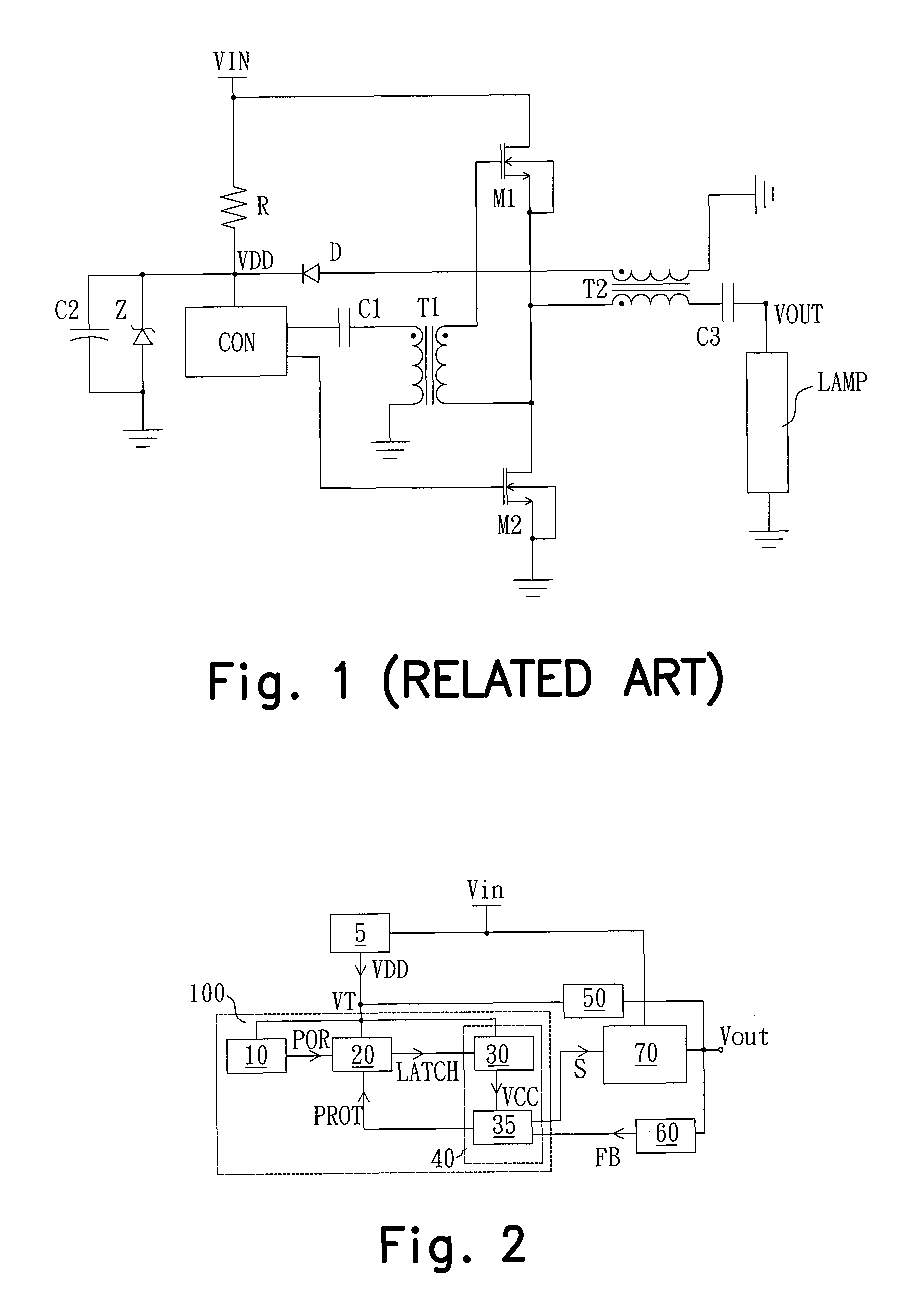
[0034]FIG. 5A and FIG. 5B are schematic circuits of power converting circuits consistent with the present invention. Referring to FIG. 5A and FIG. 5B, the power converting circuit includes a controller, a start circuit 205, a voltage converting device 250, a feedback circuit, a converting circuit 270, wherein the feedback circuit includes a first feedback unit 260a and a second feedback unit 260b. The power converting circuit converts an input voltage Vin to an output voltage Vout to drive a lamp 280. The start circuit 205 includes a capacitor and a Zener diode coupled in parallel and a starting resistor Rin coupled to the input voltage Vin. One terminal of the start circuit 205 is grounded, and another one of the start circuit 205 is coupled to the input voltage Vin through the starting resistor Rin. After the input voltage Vin is inputted to the power converting circuit, the capacitor inside the start circuit 205 starts to store electric power and generates a driving voltage VDD ...


PUM


Abstract

A controller which receives electric power required for operating through a driving voltage terminal and controls a converting circuit to convert an input voltage into an output voltage is provided. The controller is latched to stop providing a part or all of functions until the input voltage is removed. Therefore, the issues of the converting circuit in related arts in shortened life-span and safety of users due to can be avoided in the present invention.

Description

CROSS-REFERENCE TO RELATED APPLICATION[0001]This application claims the priority benefit of Taiwan application serial no. 98119296, filed Jun. 10, 2009. The entirety of the above-mentioned patent application is hereby incorporated by reference herein and made a part of specification.BACKGROUND OF THE INVENTION[0002]1. Field of the Invention[0003]The present invention generally relates to a power converting circuit and a controller thereof, and more particularly, to a power converting circuit having latching and protecting functions and the controller thereof.[0004]2. Description of Related Art[0005]Current power supplies are mainly classified into linear power supplies (LPS) and switching power supplies (SPS). The LPS has a simple circuit, small ripples, and less electromagnetic interference (EMI). However, electric devices in the circuit are large, so that volume of the circuit is large, weight thereof is heavy, and further, conversion efficiency thereof is low. On the contrary, th...

Claims


Application Information

Patent Timeline
Patent Type & Authority Patents(United States)
IPC IPC(8): G05F1/00H05B37/02H05B39/04H05B41/36H05B45/50
CPCH02M1/36H05B33/0887H05B41/2983Y10S315/05H05B45/50
Inventor YU, CHUNG-CHESHIU, SHIAN-SUNGLI, HAI-PO
Owner GREEN SOLUTION TECH CO LTD
Why Eureka
Try Eureka