
Simulated fast recharge of power supply

a technology of power supply and fast charging, which is applied in the direction of emergency power supply arrangement, transportation and packaging, metal working apparatus, etc., can solve the problems of long charging time and nuisance to users, and achieve the effect of short charging time, short recharging time, and long charging tim

Inactive Publication Date: 2012-03-20
KONINK PHILIPS ELECTRONICS NV
View PDF13 Cites 7 Cited by
  • Summary
  • Abstract
  • Description
  • Claims
  • Application Information

AI Technical Summary

Benefits of technology

This approach reduces charging time to approximately 30 seconds, eliminating the need for a mains supply option, reducing manufacturing costs and weight, while ensuring the power supply is available for emergency use.

Problems solved by technology

This long charging time is a nuisance to the user, especially when he is in a hurry.

Method used


Image

  • Simulated fast recharge of power supply
  • Simulated fast recharge of power supply
  • Simulated fast recharge of power supply

Examples


Embodiment Construction

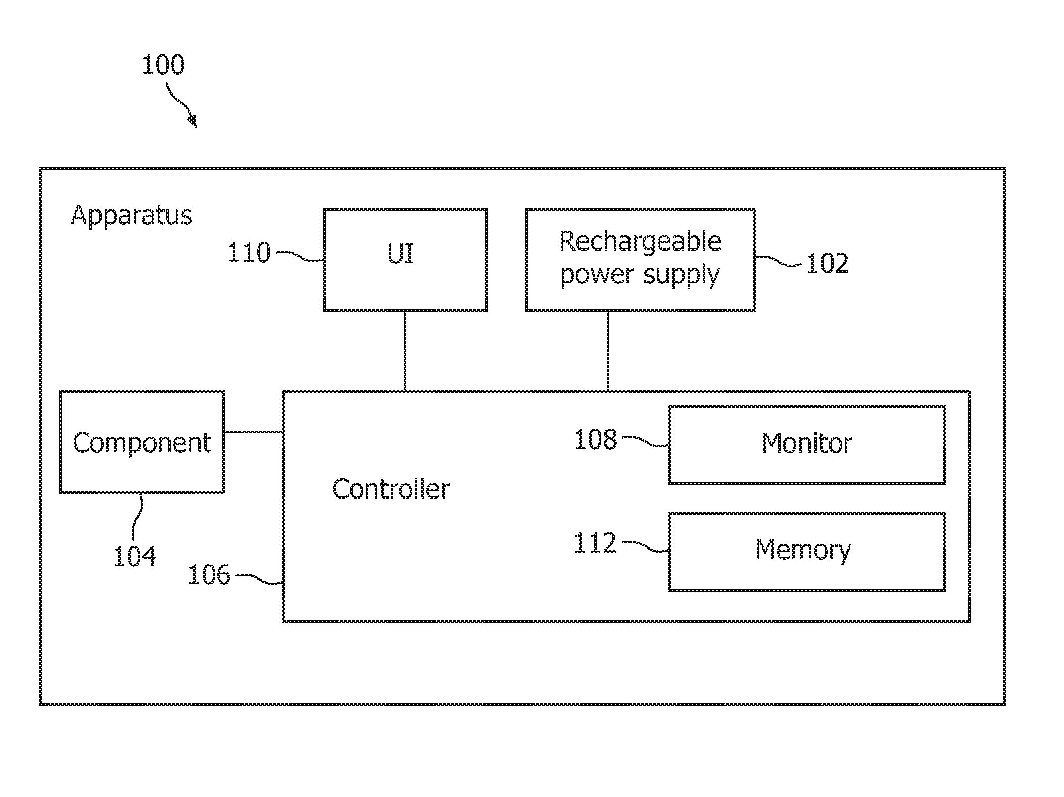
[0015]A quick-charge function is a known feature of rechargeable apparatuses, such as shavers. The purpose of this feature is to indicate when there is enough energy in the rechargeable battery for an operational cycle, e.g. one shave. If the battery is completely discharged, it takes some time before this amount of energy has been supplied to the battery. Usually, the quick-charge time for shavers is specified to be between 3 and 6 minutes. The invention describes how a quick-charge time of approximately 30 seconds can be realized for shavers. With this very short quick-charge time, it is no longer necessary to offer the option of operating the apparatus directly from the mains supply. The invention therefore offers an ergonomic advantage to its user. As another advantage, the invention makes new designs feasible that can do without a power-plug inlet construction at the apparatus, thus reducing weight and manufacturing costs.

[0016]The invention will be described hereinafter within...


PUM


Abstract

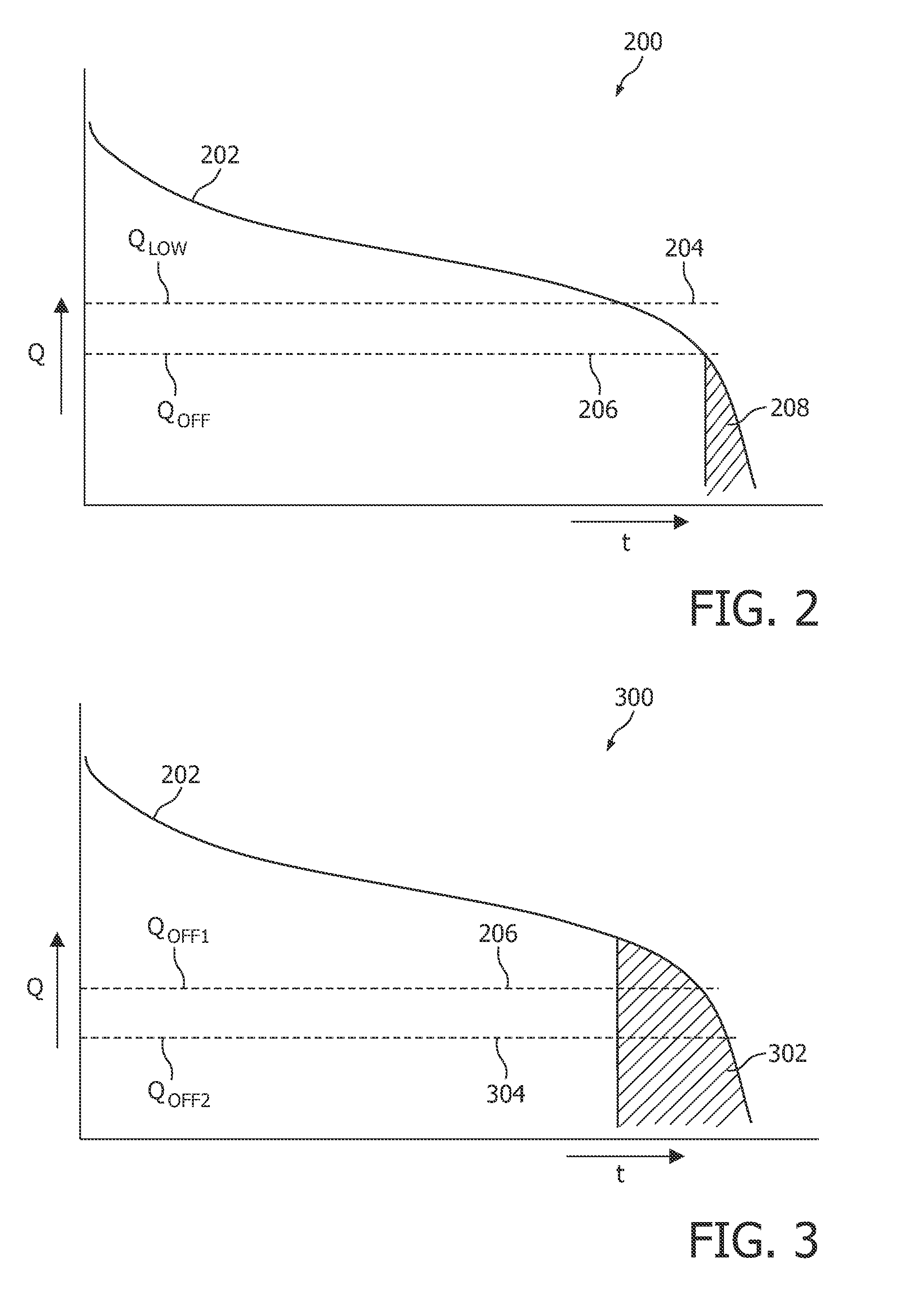
A fraction of the battery energy is kept in reserve during operational use of a battery-powered apparatus. The motor of the apparatus is switched off when the battery has discharged to the level of this reserve fraction. The reserve is made available again for operational use when the user has recharged the apparatus for a little while. This approach 5 simulates a super fast charging operation.

Description

FIELD OF THE INVENTION[0001]The invention relates to an apparatus having a rechargeable power supply. The invention also relates to a device comprising a controller for managing the power supply of the apparatus.BACKGROUND OF THE INVENTION[0002]Such apparatuses are well-known in the art, examples of which are described below.[0003]U.S. Pat. No. 4,536,757, owned by Philips Electronics and herein incorporated by reference, discloses a device for signaling a specific charge condition of an accumulator battery incorporated in a battery-powered apparatus, such as a shaver equipped with a rechargeable battery. The device comprises a comparator circuit for comparing the battery voltage with a reference voltage, a switching circuit controlled by the comparator circuit, and an indicator controlled by the switching circuit. The signaling point, i.e. the charging level of the battery at which the switching circuit responds, may be selected so that, at the instant of signaling, the battery char...

Claims


Application Information

Patent Timeline
Patent Type & Authority Patents(United States)
IPC IPC(8): H02J7/04H02J7/16
CPCB26B19/3873B26B19/388H02J9/002
Inventor HEERINGA, SCHELTEBISSCHOP, OEDILIUS JOHANNES
Owner KONINK PHILIPS ELECTRONICS NV
Learn More