
Location estimation system, method and program

a technology of location estimation and system, applied in the direction of direction finders, instruments, measurement devices, etc., can solve the problems of deterioration, location cannot be highly accurate, and the accuracy of location measurement is likely to be extremely deteriorated, so as to improve the estimation accuracy of the system

Inactive Publication Date: 2012-03-20
IBM CORP
View PDF10 Cites 3 Cited by
  • Summary
  • Abstract
  • Description
  • Claims
  • Application Information

AI Technical Summary

Benefits of technology

The present invention provides a method for improving the accuracy of estimating a location based on the strengths of radio signals from multiple sources. This is achieved by preparing data sequences of the radio signals and using an algorithm to represent the relationships between them. The method also involves calculating the affinity between data sequences using a function, and comparing it with the affinity of data sequences not arranged in chronological order. The highest plausibility score is chosen as the predicted location. The invention also uses an asymptotic exponential attenuation function in the affinity calculation.

Problems solved by technology

However, simple application of the triangulation method often leads to extreme deterioration in the accuracy of the location measurement.
Such deterioration is likely to occur especially in the case of a location measurement in an indoor environment containing a large number of reflectors and obstacles.
This is because such a large number of reflectors and obstacles cause reflected waves to interfere with each other in some cases, or, block all the direct paths between a radio signal receiver and radio signal generation sources, thereby causing the radio signal receiver to receive only reflected waves.
However, the calculation method used in triangulation is relatively simple, and hence, a location cannot be measured highly accurately with the method using triangulation even when various kinds of correction means are employed.
However, no satisfactory results were obtained by directly applying the disclosed method without modification, to estimate a location based on the strengths of radio signals received from multiple radio signal generation sources.

Method used


Image

  • Location estimation system, method and program
  • Location estimation system, method and program
  • Location estimation system, method and program

Examples


Embodiment Construction

[0028]Hereinbelow, an embodiment of the present invention will be described with reference to the drawings. For convenience of description, a case where the invention is applied to the label propagation method will be primarily described. However, it should be understood that the application field of the invention is not limited to the label propagation method. The invention is also applicable to a more general nearest neighbor decision method, or to an even more general method of estimating a location on the basis of neighborhood relationship. It should also be understood that the embodiment is given only for describing a best mode of the invention, and that the scope of the invention should not be limited to the description of the embodiment. In addition, unless otherwise stated, the same reference numerals indicate the same elements throughout the drawings.

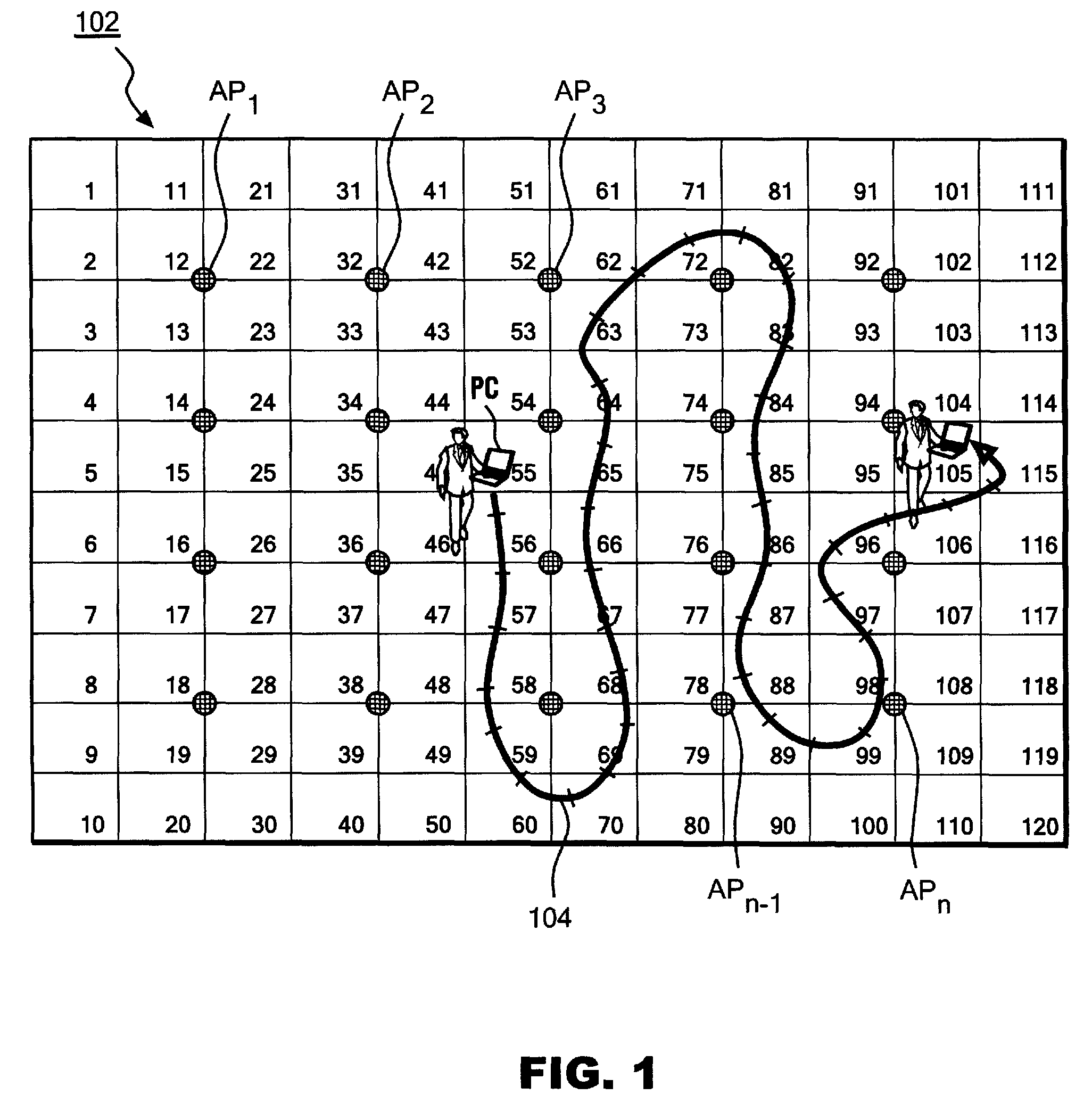
[0029]FIG. 1 is an illustration showing a general outline of a location estimation system using multiple radio signal sources...


PUM


Abstract

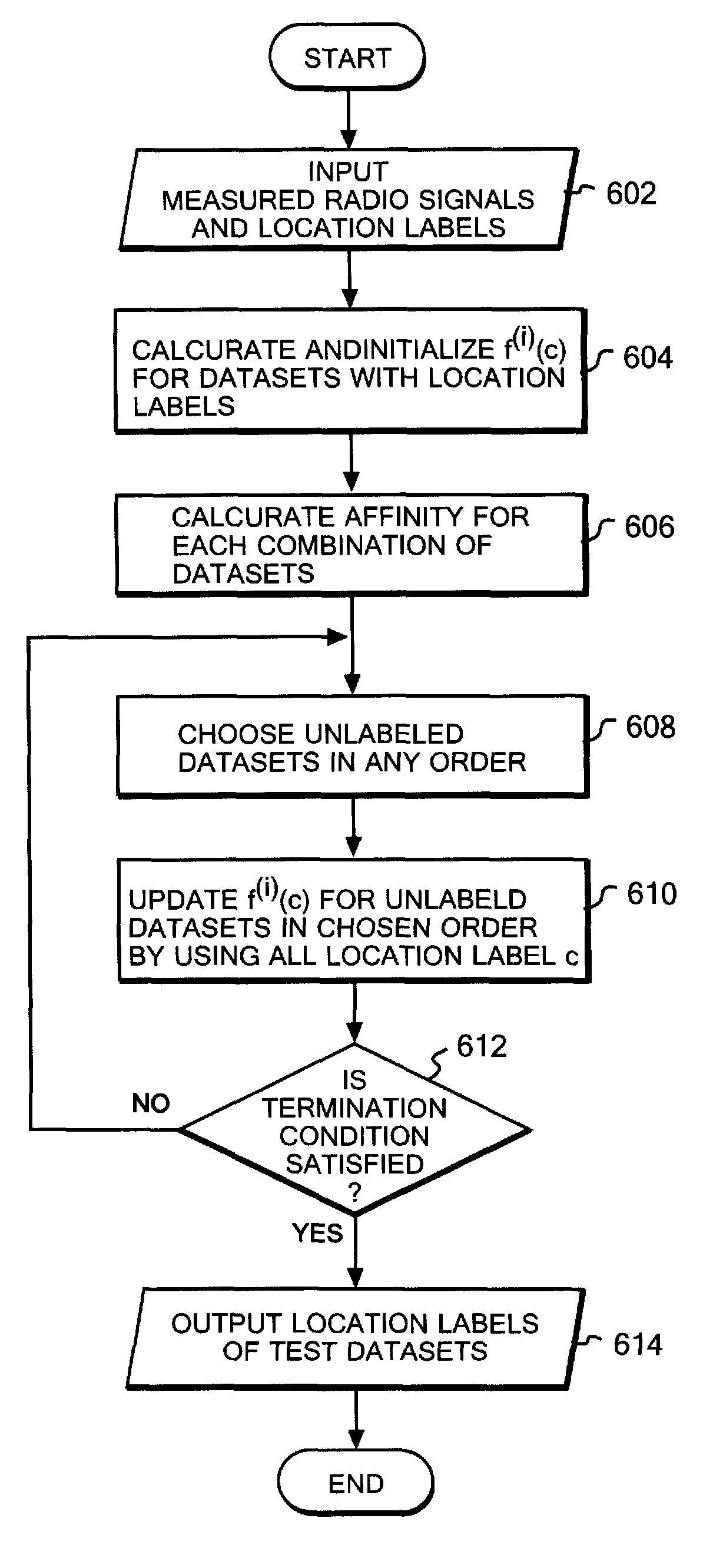
A location estimation method using label propagation. The achieved location estimation method is robust to variations in radio signal strengths and is highly accurate by using the q-norm (0<q<1), especially, for calculating the similarities among radio signal strength vectors. The accuracy in location estimation is further improved by putting more importance on the time-series similarities. Specifically, the time-series similarity is calculated by using time-series values indicating the temporal order of radio signal strengths during the measurement. If the time-series similarity is larger than the similarity between the radio signal strength vectors, the time-series similarity is preferentially used. The exponential attenuation function can also be used for calculating the similarities, instead of the q norm (0<q<1).

Description

CROSS REFERENCE TO RELATED APPLICATION[0001]This application claims priority under 35 U.S.C. §119 from Japanese Patent Application No. 2007277207 filed Oct. 25, 2007, the entire contents of which are incorporated herein by reference.BACKGROUND OF THE INVENTION[0002]1. Field of the Invention[0003]The present invention relates to a system, a method, and a program for detecting a location by receiving radio signals from multiple radio signal generation sources. More specifically, the present invention relates to a system, a method and a program for estimating location data, of a given place, associated with radio strengths, on the basis of known location data associated with radio strengths recorded in advance.[0004]2. Description of Related Art[0005]There has heretofore been a demand to track, in a room, movement of an object provided with a radio signal receiver. For example, a technique called trace analysis has been carried out in a supermarket by tracking movement of a special inf...

Claims


Application Information

Patent Timeline
Patent Type & Authority Patents(United States)
IPC IPC(8): G01S5/02G01S3/02
CPCG01S5/0252G01S5/02521
Inventor HIDO, SHOHEIIDE, TSUYOSHIKASHIMA, HISASHISUZUKI, SHOKOTAJIMA, AKIRATAKAHASHI, RIKIYATAKAHASHI, TOSHIHIROTSUBOI, YUTA
Owner IBM CORP
Learn More