Speaker device
a technology of speaker and speaker body, which is applied in the direction of transducer details, electrical transducers, electrical apparatus, etc., can solve the problems of relative deterioration of the quality of the reproduced sound, relative difficulty in managing a thinner and larger sound volume loudspeaker, etc., and achieves simple structure, simple configuration, and simple structure
- Summary
- Abstract
- Description
- Claims
- Application Information
AI Technical Summary
Benefits of technology
Problems solved by technology
Method used
Image

Examples
first embodiment
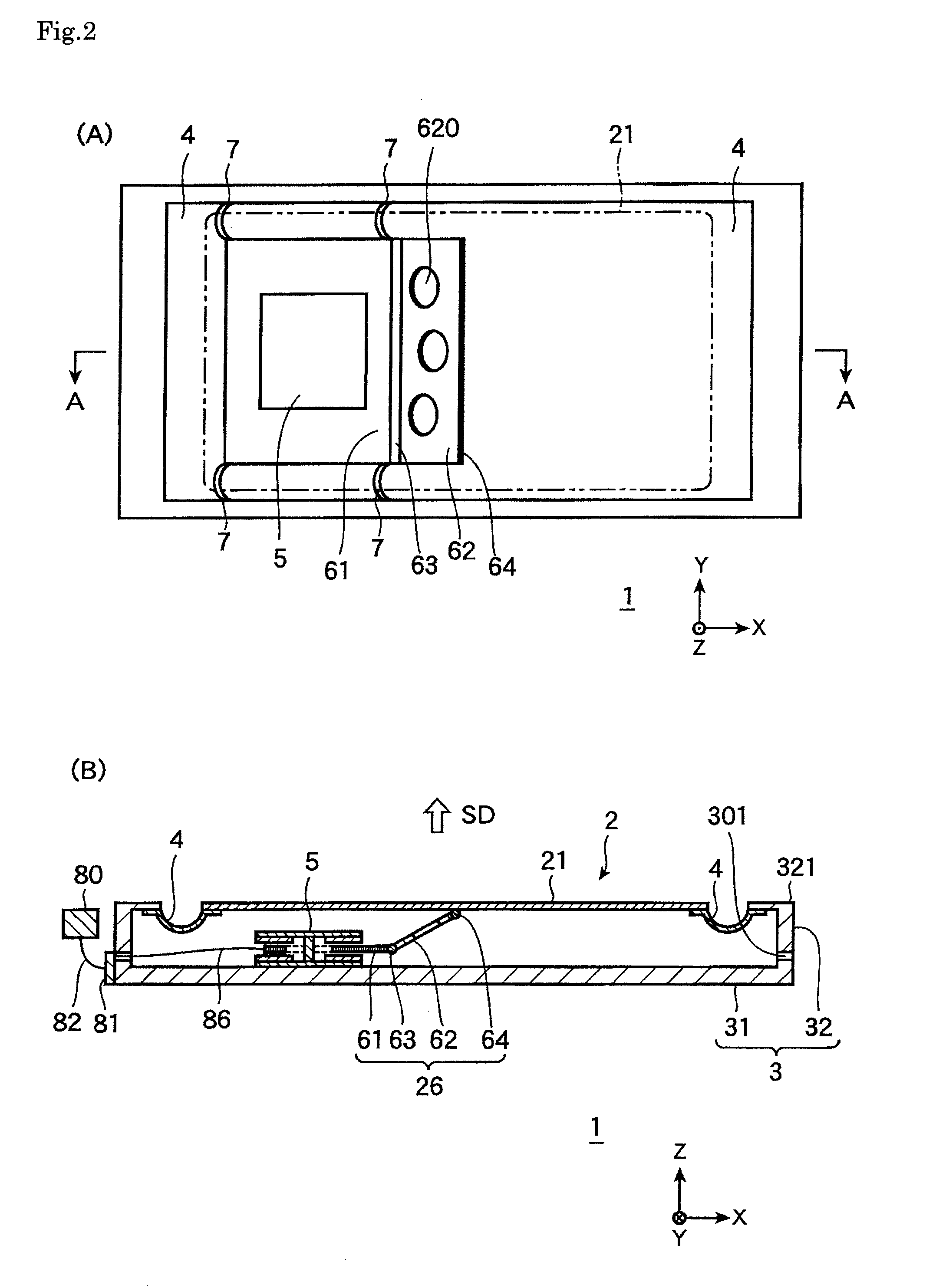
[0042]FIGS. 2A and 2B are diagrams illustrating the speaker device 1 according to a first embodiment of the present invention. Specifically, FIG. 2A is a front view of the speaker device 1 according to the first embodiment of the invention (the diaphragm is not shown) and FIG. 2B is a cross-sectional view of the speaker device 1 shown in FIG. 2A taken along the A-A line.
[0043]FIG. 3 is an enlarged perspective view of the vicinity of the magnetic circuit 5 of the speaker device 1 shown in FIGS. 2A and 2B. FIG. 4 is an exploded perspective view of the magnetic circuit 5 of the speaker device 1 shown in FIG. 3. FIG. 5 is a cross-sectional view of the speaker device 1 shown in FIGS. 2A and 2B. The sound emission direction (SD) of the diaphragm 21 of the speaker device 1 is defined as Z-axis direction, the lengthwise direction (driving direction of the driving part) as X-axis direction, and the direction perpendicular to the Z-axis and the X-axis as Y-axis direction.
[0044]As shown in FIG...
second embodiment
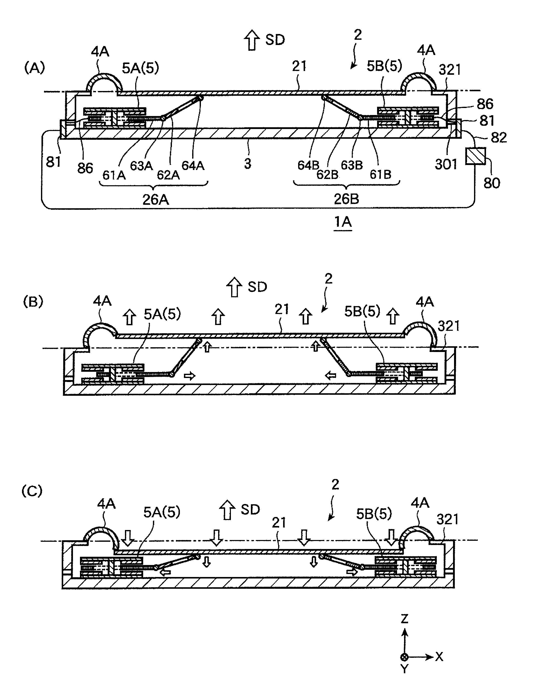
[0120]FIGS. 7A to 7C illustrate the speaker device 1A according to a second embodiment of the present invention. Specifically, FIG. 7A is a cross-sectional view of the speaker device 1A when the diaphragm is not displaced with respect to a reference position. FIG. 7B is a cross-sectional view of the speaker device 1A when the diaphragm is displaced to the sound emission side with respect to the reference position. FIG. 7C is a cross-sectional view of the speaker device 1A when the diaphragm is displaced to the side opposite of the sound emission side. The same configurations in the first embodiment are not described here.
[0121]The speaker device 1A of this embodiment includes plural magnetic circuits and driving members, specifically two magnetic circuits 5A and 5B and two driving members 26A and 26B. The driving member 26A includes a driving part 61A in which a voice coil is formed, an angle conversion and transmission part 62A, a folding part 63A, a folding part 64A, whereas the d...
third embodiment
[0128]FIGS. 8A to 8C are diagrams illustrating a speaker device 1B according to a third embodiment of the present invention. Specifically, FIG. 8A is a cross-sectional view of the speaker device 1B when a diaphragm is not displaced with respect to a reference position. FIG. 8B is a cross-sectional view of the speaker device 1B when the diaphragm is displaced to the sound emission side with respect to the reference position. FIG. 8C is a cross-sectional view of the speaker device 1B when the diaphragm is displaced on the side opposite of the sound emission side with respect to the reference position. The same configurations in the first and second embodiments are not described here.
[0129]As shown in FIGS. 8A to 8C, in the speaker device 1B of this embodiment, the angle conversion and transmission parts 62A and 62B are foldably joined to the central portion (barycentric position) of the diaphragm 21. Also, compared with the second embodiment, the magnetic circuits 5A and 5B are arrang...
PUM
 Abstract
Description
Claims
Application Information
 - R&D
- Intellectual Property
- Life Sciences
- Materials
- Tech Scout
- Unparalleled Data Quality
- Higher Quality Content
- 60% Fewer Hallucinations
Browse by: Latest US Patents, China's latest patents, Technical Efficacy Thesaurus, Application Domain, Technology Topic, Popular Technical Reports.
© 2025 PatSnap. All rights reserved.Legal|Privacy policy|Modern Slavery Act Transparency Statement|Sitemap|About US| Contact US: help@patsnap.com